Apparatus for rotation of a large body about an axis

a large body and rotating technology, applied in the direction of machine supports, manufacturing tools, lighting and heating apparatus, etc., can solve the problems of imperceptible short and achieve the effect of improving the control of the rotation, prolonging the expansion, and shortening the time for such rapid actuation and de-actuation

Inactive Publication Date: 2009-09-03
KANEFF STEPHEN
View PDF10 Cites 2 Cited by
  • Summary
  • Abstract
  • Description
  • Claims
  • Application Information

AI Technical Summary

Benefits of technology

[0021]It is an object of the present invention to provide a new mechanism for rotating a large body about an axis, which is suitable for use with large dish antennae, and which (a) is both less costly and more reliable than both the conventional motor and pinion arrangement and the “walking ram” mechanism described above, and (b) is also suitable for the rotation of other large bodies.
[0024]The throw of the expansion and contraction device will normally be variable, and the extent of the predetermined throw will be chosen to suit the conditions under which the body is being rotated. Therefore, if essentially continuous rotation of the body is required, a short throw of the expansion and contraction device will 15 be adopted, with rapid actuation and de-actuation of the clamp and of the expansion and contraction device. (With modem switching techniques, the time for such rapid actuation and de-actuation can be imperceptibly short.) If the present invention is to be used with a solar energy collector having a large dish antenna which tracks the sun, for which step-wise rotation is acceptable, a longer throw of the expansion and contraction device can be adopted, and a substantial improvement over the control of the rotation, compared with the “walking ram” arrangement described above, can be achieved.

Problems solved by technology

(With modem switching techniques, the time for such rapid actuation and de-actuation can be imperceptibly short.)

Method used


Image

  • Apparatus for rotation of a large body about an axis
  • Apparatus for rotation of a large body about an axis
  • Apparatus for rotation of a large body about an axis

Examples


Embodiment Construction

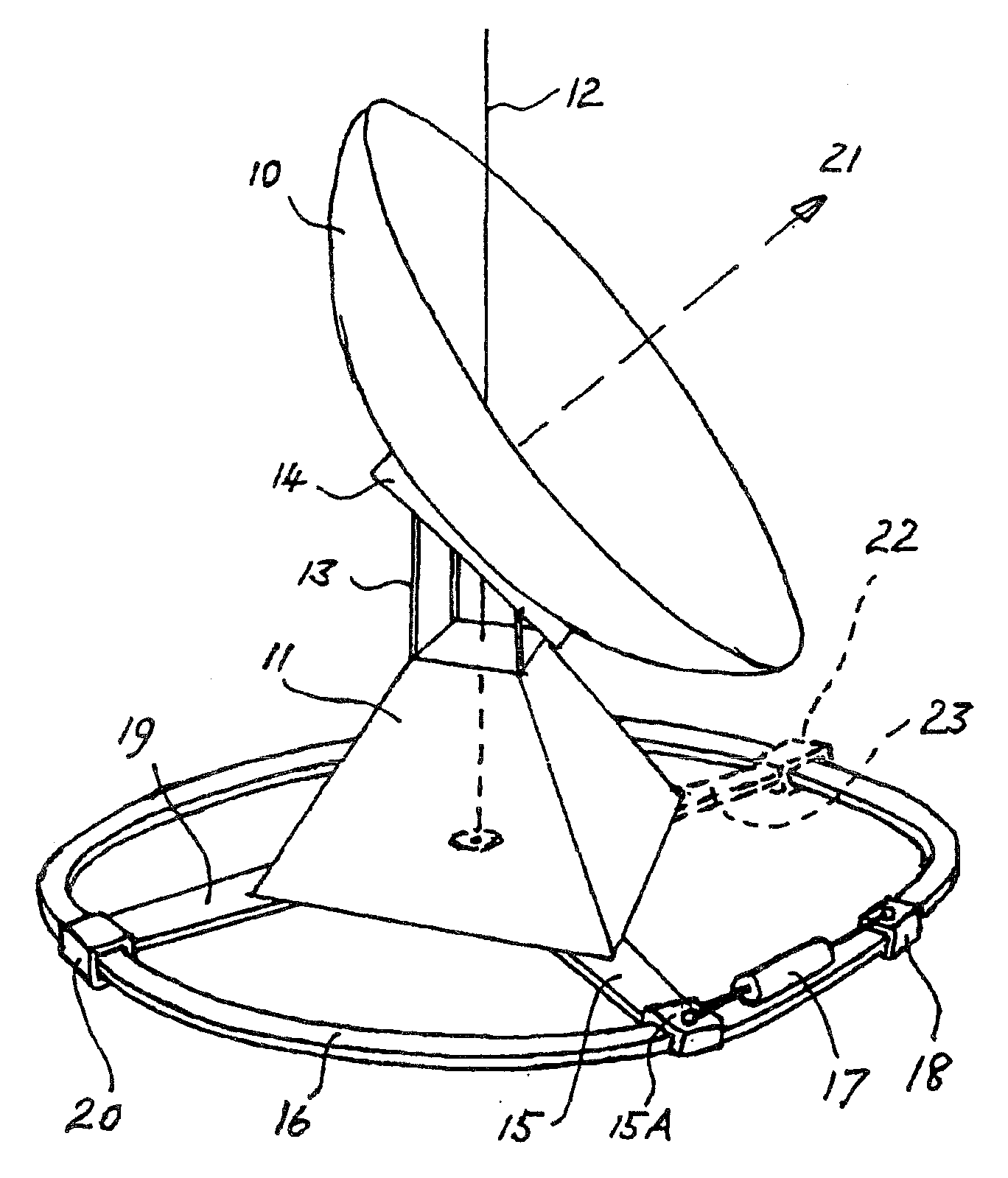
[0055]In this specification, including the claims, “directional” terms (such as “top”, “below”, “uppermost” and the like) will be used in the sense that these terms would have with reference to an embodiment of the invention positioned as shown in FIG. 1 of the accompanying drawings.

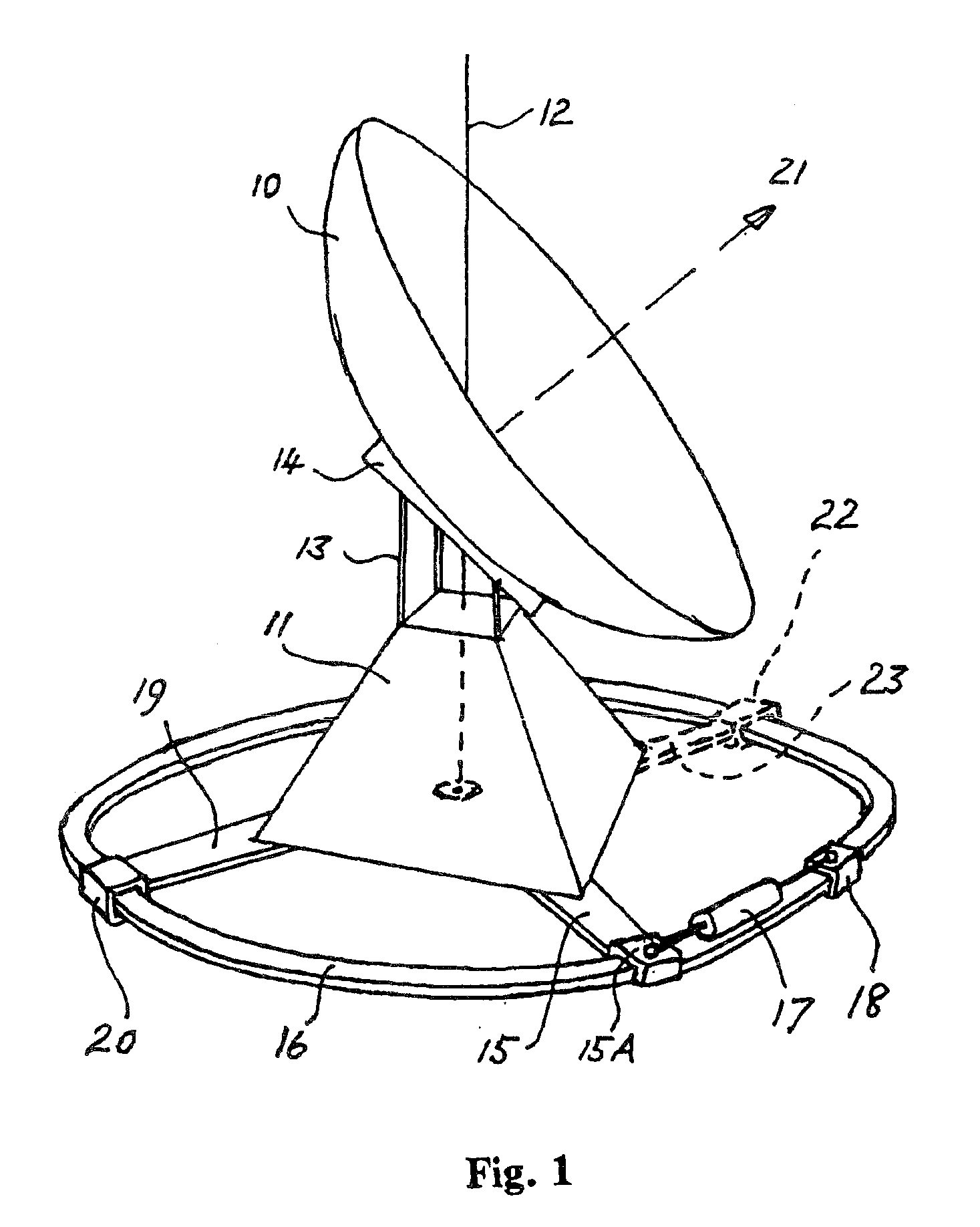
[0056]FIGS. 1 and 2 each show, schematically, a dish antenna to be rotated about a vertical axis 12. The dish antenna for which the present invention was developed is a large solar energy collector which has been assembled at The Australian National University, in Canberra, Australia. That solar energy collector has been described in the specifications of, inter alia, U.S. Pat. Nos. 5,757,335 and 5,934,271. However, it is emphasized that the solar energy collector and the dish antennae featured in FIGS. 1 and 2 are only examples of a rotatable structure with which the present invention may be used, and the present invention is not limited in its application to solar energy collectors generally, or to rot...


PUM


Abstract

Apparatus for the rotation of a large body, such as the base frame of a solar energy collector having a large reflective dish, about an axis utilizes a ring member or arcuate member. An actuator clamp is movable along the ring or arcuate member when it is not clamped to it. The actuator clamp is connected to one end of an expansion and contraction device, such as a hydraulic ram. The other end of the hydraulic ram is connected to the body, to a projection from the body, or to a rigid arm that is securely connected to the body. With the actuator clamp firmly clamped to the ring or arcuate member, actuation of the hydraulic ram causes the body to rotate about the axis.

Description

CROSS-REFERENCE TO RELATED APPLICATION[0001]This application is a continuation-in-part of U.S. patent application Ser. No. 10 / 577,689, filed Apr. 28, 2006, which was derived from International (PCT) patent application No. PCT / AU2004 / 001474.TECHNICAL FIELD[0002]This invention concerns the rotation of a body about an axis. More particularly, it concerns the controlled rotation (which includes partial rotation) of a large body about an axis, and (in one special situation) linear movement of a large body.[0003]This invention was developed to provide effective actuation and control of the rotation of structures on which are mounted large dish antennae, such as the dish antennae used in radio telescopes, solar energy collectors and satellite communication systems, and in particular the large solar energy collector dish antennae described in the specifications of U.S. Pat. Nos. 5,757,335 and 5,934,271, and corresponding Australian patents Nos. 677,257 and 700,607. For this reason, the larg...

Claims


Application Information

Patent Timeline
Patent Type & Authority Applications(United States)
IPC IPC(8): H01Q3/00B25B5/00F15B15/02F15B15/06F16B2/12F16M11/08F16M11/18F24J2/54F24S23/71H01Q1/12
CPCF16B2/12F16M11/08F16M11/18F16M2200/041F24J2/12Y02E10/47F24J2002/5437F24J2002/5479H01Q1/12H01Q1/125Y02E10/42F24J2/542F24S23/71F24S2030/145F24S30/452F24S2030/11Y02E10/40
Inventor KANEFF, STEPHEN
Owner KANEFF STEPHEN
Why Eureka
Try Eureka