Eureka AIR delivers breakthrough ideas for toughest innovation challenges, trusted by R&D personnel around the world.

Image Compression Apparatus and Image Expansion Apparatus

Inactive Publication Date: 2009-09-03
KONICA MINOLTA BUSINESS TECH INC
View PDF3 Cites 3 Cited by
  • Summary
  • Abstract
  • Description
  • Claims
  • Application Information

AI Technical Summary

Benefits of technology

[0011]Whether to be a first compressed data or a second compressed data can be determined by checking that the data arranged in the header section is formed in an ascending order or descending order. Thus, it is not necessary to separately add information, which shows a difference in compression technologies, and an increase in data volume of this portion can be prevented.

Problems solved by technology

In an image on a sheet, a character area and a photographic area are intermingled in many cases, and when the image on the sheet is evenly compressed / expanded with a compression technology, image quality may greatly deteriorate in a specific area.
However, when information for discriminating the compression technology per block is separately added, the data volume of that portion will increase and reduction of the compression ratio will occur.
H11-75069, when the compression technology is switched, data volume after compression respectively differs and there is a problem that the management of the breaks of the block becomes complicated.

Method used


Image

  • Image Compression Apparatus and Image Expansion Apparatus
  • Image Compression Apparatus and Image Expansion Apparatus
  • Image Compression Apparatus and Image Expansion Apparatus

Examples


Embodiment Construction

[0022]Hereafter, an embodiment of the present invention will be described based on drawings.

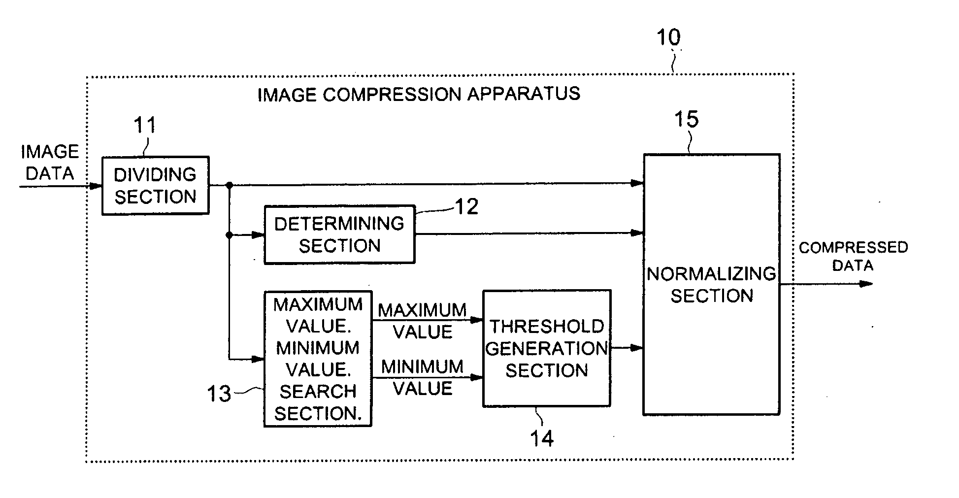
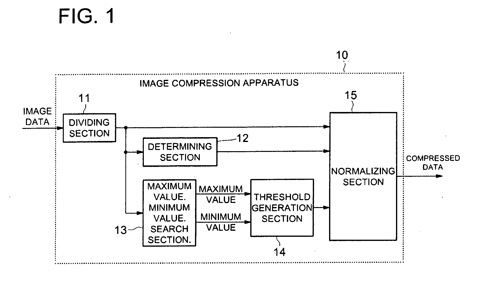
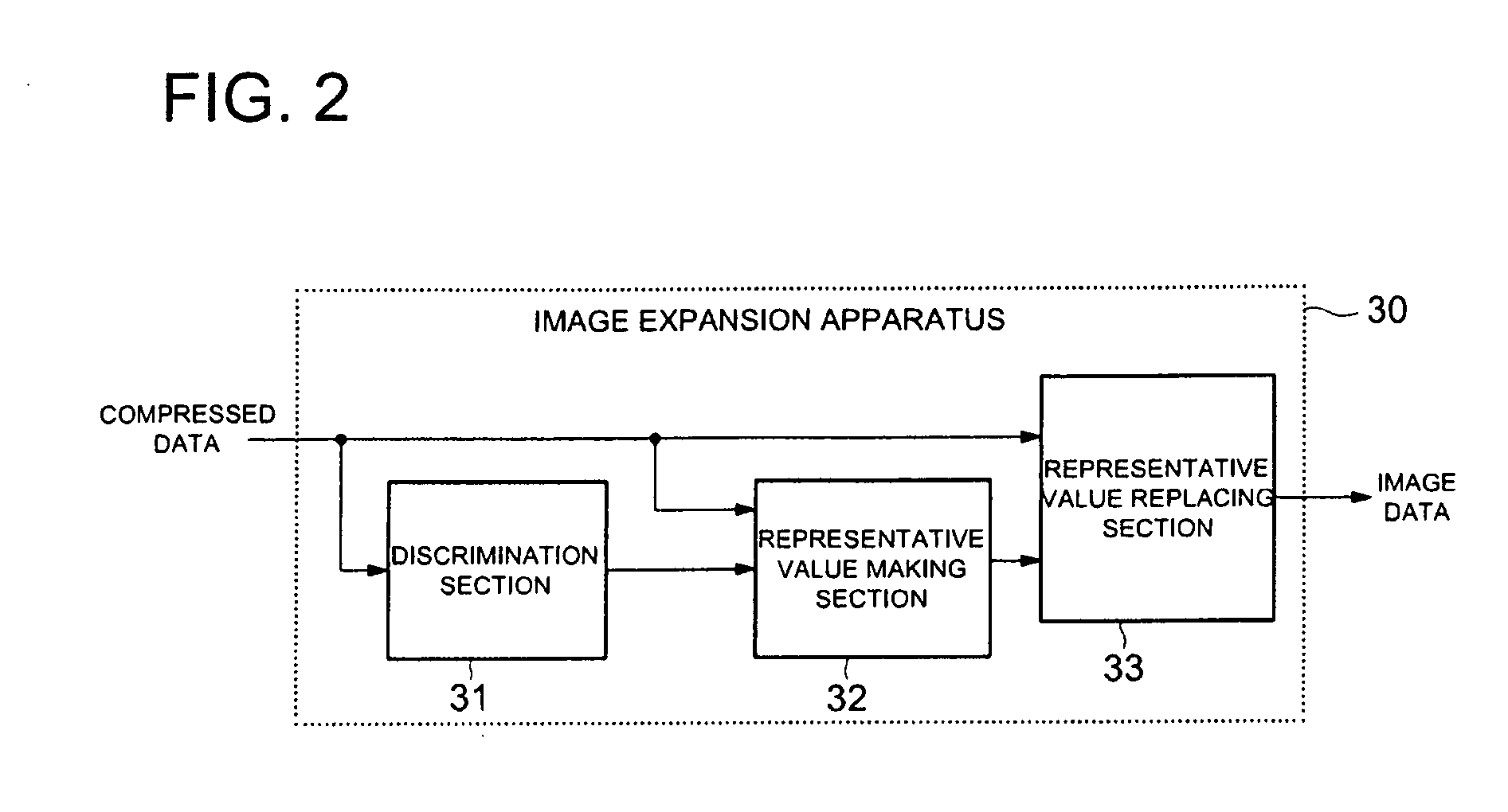
[0023]FIG. 1 shows a structure of an image compression apparatus 10 related to an embodiment of the present invention, and FIG. 2 shows a structure of an image expansion apparatus 30 related to an embodiment of the present invention. The image data of an image to be compressed is inputted to the image compression apparatus 10. This image is divided into blocks, each block of which having a predetermined number of pixels. The image compression apparatus 10 has a function for outputting the compressed data to which each block has been compressed. The image expansion apparatus 30 has a function, which expands the compressed data generated by the image compression apparatus 10.

[0024]For example, in a multi-function peripheral (MFP) provided with a copy function and a print function of a document, the image compression apparatus 10 is used for the compression processing at the time of compressing ...


PUM


Abstract

An image compression apparatus includes: a dividing section for dividing an image to be compressed into blocks, each of which has a predetermined number of pixels having respective gradation values; a determining section for determining whether the block is a first kind block, in which a number of kinds of gradation values of the predetermined number of pixels belonging to the block is not greater than N (where N is an integer which is equal to 2 or greater) for each block divided and obtained by the dividing section; and a normalizing section which generates one of a first kind compressed data and a second kind of compressed data depending on the result of the determination.

Description

RELATED APPLICATION[0001]This application is based on Japanese Patent Application No. 2008-47898 filed on Feb. 28, 2008 in Japanese Patent Office, the entire content of which is hereby incorporated by reference.BACKGROUND[0002]1. Field of the Invention[0003]The present invention relates to an image compression apparatus and an image expansion apparatus, which compresses / expands image data, particularly relates to an image compression apparatus and an image expansion apparatus, which compresses / expands image to be compressed by a block unit having a predetermined number of pixels.[0004]2. Description of Related Art[0005]In an image on a sheet, a character area and a photographic area are intermingled in many cases, and when the image on the sheet is evenly compressed / expanded with a compression technology, image quality may greatly deteriorate in a specific area. Then, the image processing apparatus, which discriminates the characteristic of the image per block and switches the compr...

Claims


Application Information

Patent Timeline
IPC IPC(8): G06K9/36
CPCH04N1/415H04N19/176H04N19/98H04N19/124H04N19/14H04N19/46
Inventor SUZUKI, TAKAYUKI
Owner KONICA MINOLTA BUSINESS TECH INC
Why Eureka
Eureka Blog
Learn More