Wind deflector for wind turbine and wind turbine incorporating same

a technology of wind turbines and wind turbines, applied in the direction of wind turbines, motors, propellers, etc., can solve the problem of less efficient turbines

Inactive Publication Date: 2009-09-03
HOPEWELL WIND POWER
View PDF0 Cites 18 Cited by
  • Summary
  • Abstract
  • Description
  • Claims
  • Application Information

AI Technical Summary

Benefits of technology

[0005]It is one object of the present invention to provide a wind deflector for a wind turbine that ov...

Problems solved by technology

This may cause the turbine to...

Method used


Image

  • Wind deflector for wind turbine and wind turbine incorporating same
  • Wind deflector for wind turbine and wind turbine incorporating same
  • Wind deflector for wind turbine and wind turbine incorporating same

Examples


Embodiment Construction

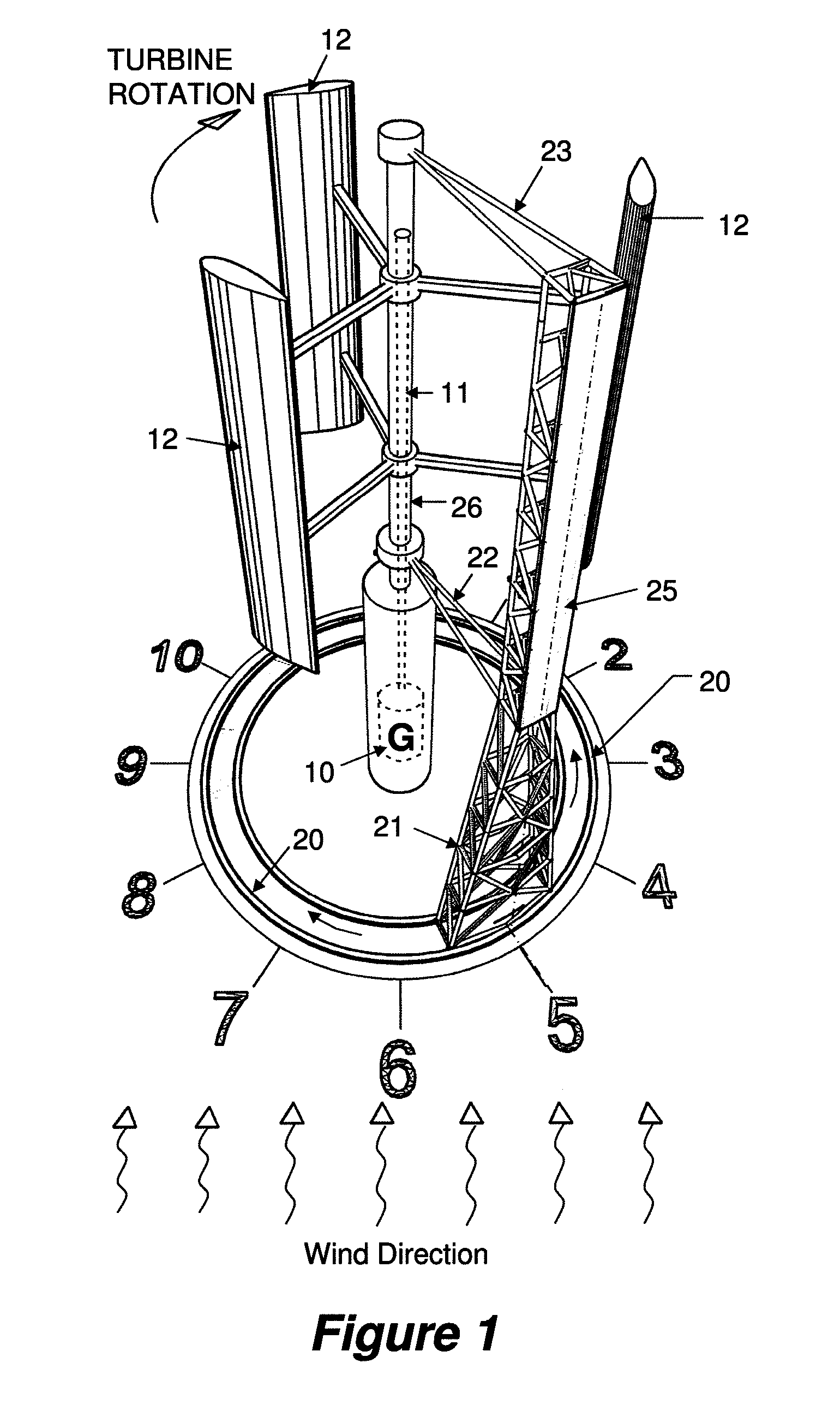
[0026]In FIG. 1 there is depicted a perspective illustration of a wind turbine with a wind deflector according to the invention. The scale of the wind turbine is not critical to the invention and it may be of any size from a small roof top wind turbine up to a large turbine having, for example, a diameter of 300 metres and a height of up to 500 metres. A wind turbine of this size has been proposed by the applicant in earlier patent applications.

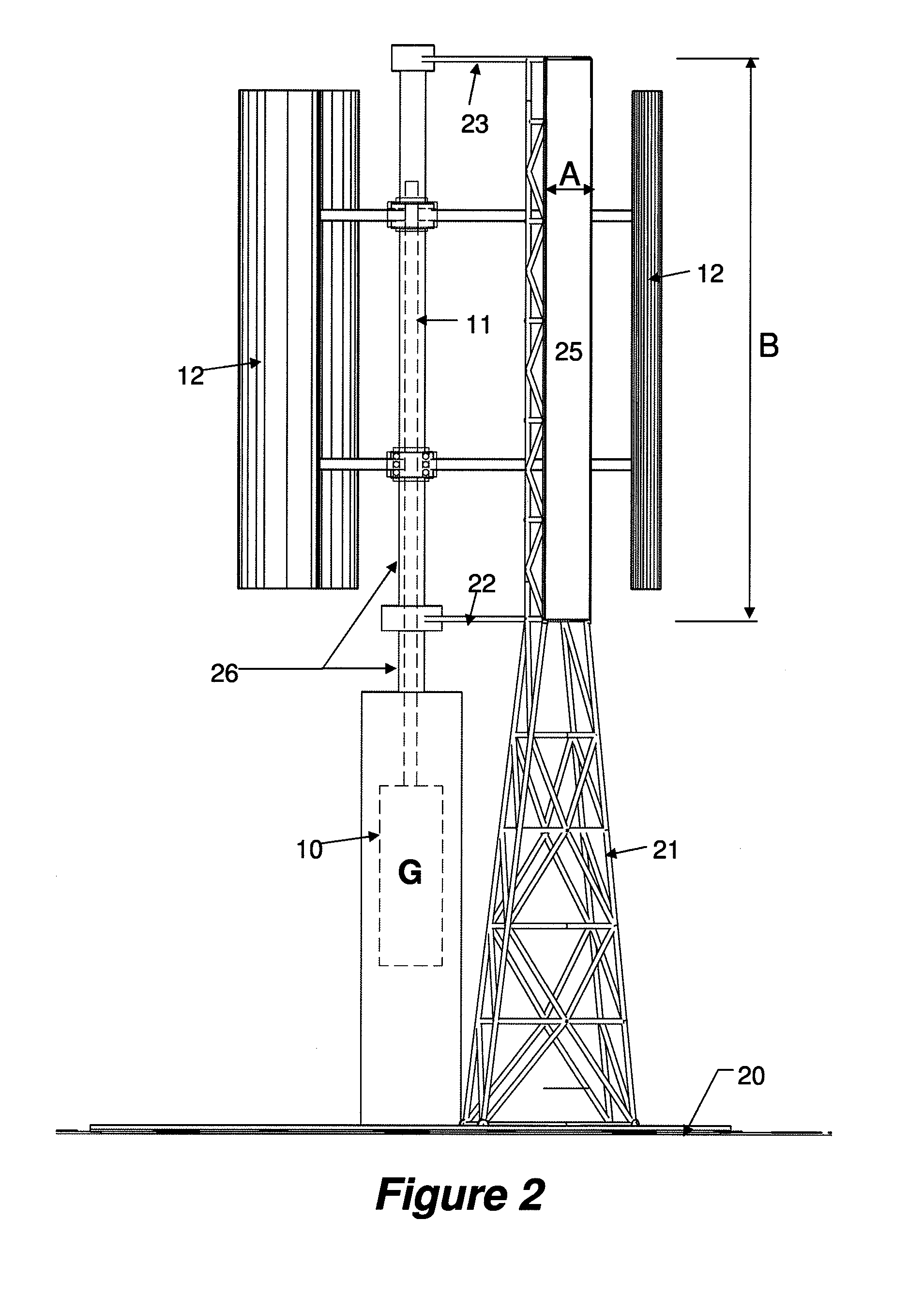
[0027]The wind turbine of FIG. 1 comprises a base housing an electricity generator 10. A stationary turbine support frame 26 extends vertically from the base and encloses a vertical rotary shaft 11 coupled to the generator. The shaft 11 is connected to three radial blade structures each supporting lift-type aerofoil shaped blades 12. The blades 12 are arranged 120 degrees apart about the rotary shaft 11. The blades 12 are acted upon by wind causing the rotary shaft 11 to rotate for generating electricity as is known in the art.

[0028]The wind ...


PUM


Abstract

A wind deflector for a wind turbine has a vertical wind deflecting surface movable in a circular path about the wind turbine for facing a prevailing wind direction.

Description

BACKGROUND TO THE INVENTION[0001]1. Field of the Invention[0002]The present invention relates to wind turbines and in particular to a wind deflector for use with a wind turbine.[0003]2. Background Information[0004]Vertical axis wind turbines are well known in the art. In a vertical axis wind turbine the main rotor shaft is arranged vertically and has radially extending arms supporting vertically arranged wind engaging blades. In a lift-type vertical axis wind turbine the blades have an aerofoil shape such that most of the rotating force comes from aerodynamic forces generated by wind passing across the aerofoils. Because the turbine rotates the aerofoils engage the wind from continuously varying directions throughout a circular path and each blade experiences both positive and negative wind power within each revolution. This may cause the turbine to be less efficient than it might be.SUMMARY OF THE INVENTION[0005]It is one object of the present invention to provide a wind deflector ...

Claims


Application Information

Patent Timeline
IPC IPC(8): F03D3/00
CPCF03D3/0445F03D3/0472Y02E10/74F05B2240/13F03D3/062Y02E10/728F05B2240/214F05B2240/912F03D3/04F03D9/25
Inventor WU, GORDON Y. S.WU, THOMAS J.WU, CAROL ANN
Owner HOPEWELL WIND POWER
Why Eureka
Try Eureka