Radiation image device

a technology of imaging device and radiation, which is applied in the direction of radioation controlled devices, television systems, instruments, etc., can solve the problem of limiting the size of each individual imaging element, and achieve the effects of reducing the formation of dead areas, high sensitivity, and high definition

Active Publication Date: 2009-09-10
HAMAMATSU PHOTONICS KK
View PDF22 Cites 3 Cited by
  • Summary
  • Abstract
  • Description
  • Claims
  • Application Information

AI Technical Summary

Benefits of technology

[0015]With the present invention, because the photodetecting portions of the respective radiation imaging elements can be juxtaposed to each other without restricting the effective image regions, the imaging characteristics within the effective image regions can be made uniform while suppressing the forming of dead areas. Thus, when a plurality of the imaging elements are combined in a buttable array to form a large-screen imaging element, the occurrence of unevenness of image and focus deviation due to the imaging elements being different can be restrained, and images can be obtained at high sensitivity and high definition even with a low radiation amount.
[0016]When the photodetecting portions are positioned so that the ends overlap as viewed from the radiation incident direction, the dead area can be lessened because the photodetecting portions can be positioned closer to each other.
[0017]Unlike the radiation imaging elements positioned at the front, with the radiation imaging elements positioned at the back, the photodetecting portions do not need to be positioned close to the edges. By disposing the photodetecting portion near the center of the substrate, the forming of a scintillator that is uniform in thickness up to the ends of the photodetecting portion is facilitated and the product yield is improved further. Especially, when radiation imaging elements of two different sizes are positioned adjacently, by positioning the larger radiation imaging element at the back, the scintillator with uniform thickness up to the ends of the photodetecting portion can be formed readily and the product yield is improved further.

Problems solved by technology

There is thus a limit to making each individual imaging element large in screen size.

Method used


Image

  • Radiation image device
  • Radiation image device
  • Radiation image device

Examples


first embodiment

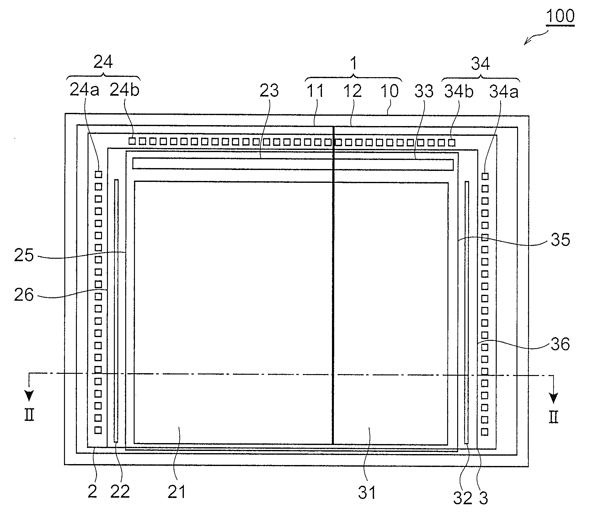
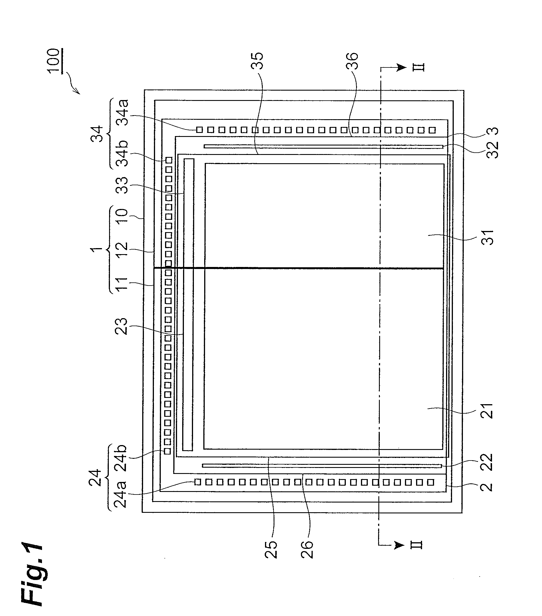
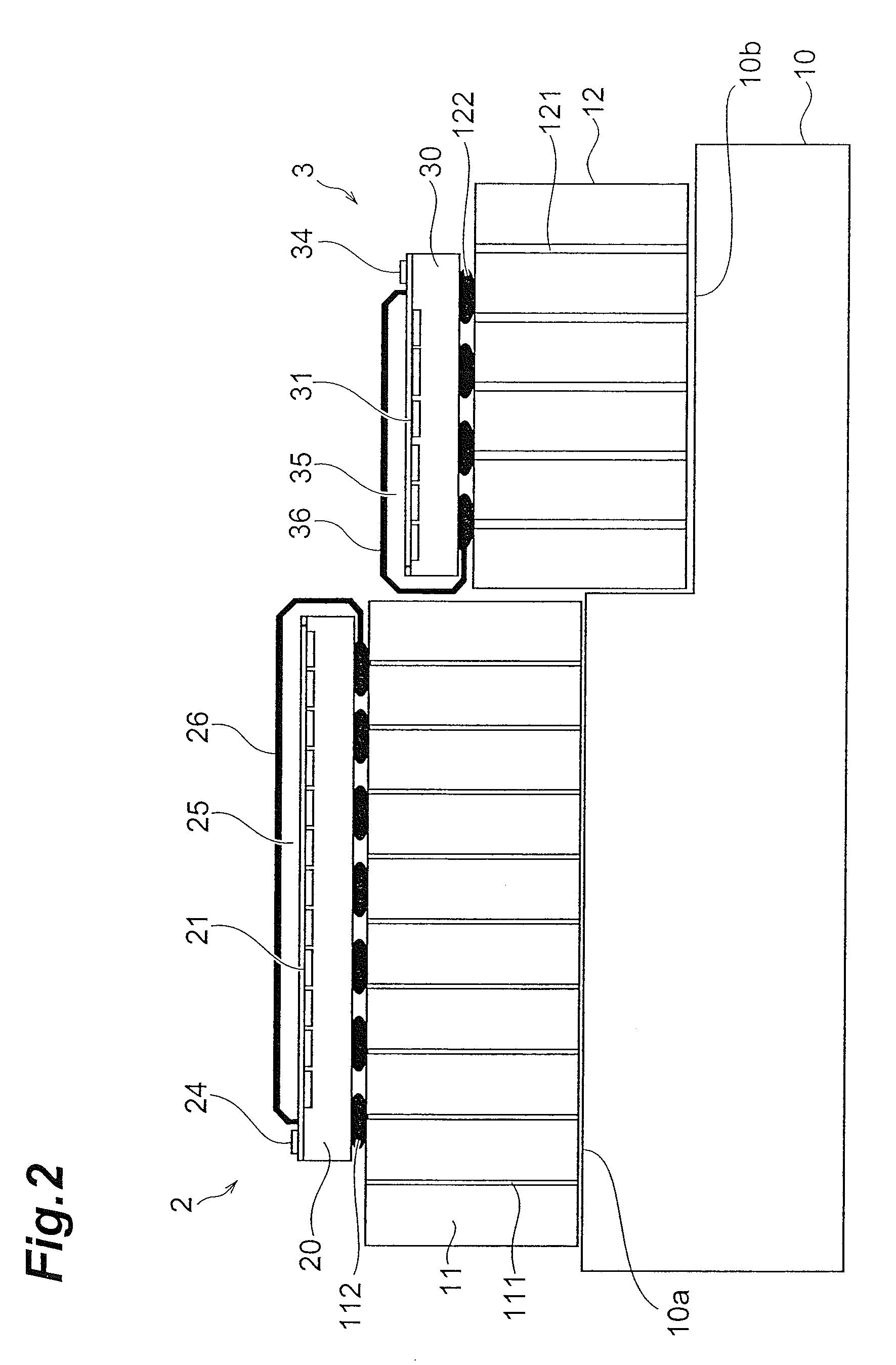
[0057]a radiation imaging device according to the present invention is shown in FIGS. 1 to 3. FIG. 1 is a front view as viewed from a radiation incident direction. FIG. 2 is a sectional view taken along line II-II of FIG. 1. FIG. 3 is an enlarged view of a boundary portion of radiation imaging elements of FIG. 2.

[0058]As shown in FIGS. 1 to 3, with the radiation imaging device 100, radiation imaging elements 2 and 3 are positioned in a stepped manner on a base 1. The radiation imaging elements 2 and 3 are MOS (Metal-Oxide Semiconductor) type image sensors formed on Si substrates 20 and 30, respectively, and are formed to rectangular plate-like shapes. Here, the Si substrate 20 has a size of 184 mm×231 mm, the Si substrate 30 has a size of 96 mm×23 mm, and both have a thickness of 725 μm.

[0059]Each of photosensitive portions (photodetecting portions) 21 and 31, which are photodetecting regions, is positioned up to vicinities of two adjacent edges of each of the top surfaces of the Si...

second embodiment

[0103]This embodiment is a modification example of the second embodiment and differs from the other embodiments in that a photosensitive portion 31a of a radiation imaging element 3a that is disposed at the back does not extend to the edge at the radiation imaging element 2 side and the interval from the photosensitive portion 31a to the end is set wider than that in the other embodiments.

[0104]Here, with the radiation imaging element 2 that is positioned at the front, in order to make small the dead area D resulting from the blocking of the other radiation imaging element 3a while securing imaging characteristics up to the end of the effective photodetecting region, the photosensitive portion 21 must be juxtaposed to the edge and the scintillator 25 must be formed at a substantially uniform thickness up to the end. Though for this purpose, it is preferable to form the scintillator 25 continuously at a substantially uniform thickness up to the side wall portion, the scintillator 25 ...


PUM

PropertyMeasurementUnit
thicknessaaaaaaaaaa
sizeaaaaaaaaaa
sizeaaaaaaaaaa

Abstract

Wiring substrates 11 and 12 are positioned on a fixed base 10 in a manner such that there is a step between the wiring substrates, and radiation imaging elements 2 and 3, respectively having scintillators 25 and 35 deposited on photosensitive portions 21 and 31, are respectively mounted on the wiring substrates 11 and 12. The radiation imaging element 2 is positioned so that its setting surface protrudes beyond a radiation incident surface of the radiation imaging element 3, and the photosensitive portion 21 of the radiation imaging element 2 and the photosensitive portion 31 of the radiation imaging element 3 are juxtaposed to a degree to which the portions do not overlap. The photosensitive portion 21 of the radiation imaging element 2 extends close to an edge at the radiation imaging element 3 side and the scintillator 25 of substantially uniform thickness is formed up to this position.

Description

TECHNICAL FIELD[0001]The present invention relates to a radiation imaging device and particularly relates to a large-scale radiation imaging device for use in such applications as mammography.BACKGROUND ART[0002]In the field of X-ray photography for medical and industrial purposes, radiation imaging systems using radiation detecting elements in place of X-ray sensitive films are coming to be used widely in recent years. Such a radiation imaging system is highly convenient in that there is no need for development as in the case of X-ray sensitive films and radiation images can be checked in real time, etc., and also provides advantages in terms of data storability and ease of handling.[0003]With a general radiation imaging system, an incident radiation image is converted to visible light, etc. (including ultraviolet rays and infrared rays) by a scintillator, and the converted light image is detected by photodetecting elements arrayed in one dimension or two dimensions and output elec...

Claims


Application Information

Patent Timeline
Patent Type & Authority Applications(United States)
IPC IPC(8): G01T1/20G01N23/04B32B7/14A61B6/00H01L27/14H01L27/146H01L31/0203H01L31/0232H01L31/09H04N5/32H04N5/321
CPCG01T1/2018H01L27/14618H01L31/0203H01L31/02322H01L2924/0002H04N5/32H01L2924/00G01T1/20189G01T1/20182G01T1/00A61B6/00H01L27/14H04N5/321
Inventor MORI, HARUMICHIHONDA, MASAHIKOKYUSHIMA, RYUJIFUJITA, KAZUKI
Owner HAMAMATSU PHOTONICS KK
Why Eureka
Try Eureka