Detection and Ranging Device and Detection and Ranging Method

a detection and ranging device technology, applied in direction finders using radio waves, multi-channel direction-finding systems using radio waves, instruments, etc., can solve the problems of increasing processing time and further increasing calculation load, inability to perform, and low reliability of target-count estimation

Inactive Publication Date: 2009-09-10
FUJITSU LTD
View PDF7 Cites 19 Cited by
  • Summary
  • Abstract
  • Description
  • Claims
  • Application Information

AI Technical Summary

Benefits of technology

The objective of this invention is to address issues with existing technologies by providing solutions that improve efficiency or performance.

Problems solved by technology

The technical problem addressed in this patent text is finding a way to estimate the optimal size of a submatrix used for evaluating the effectiveness of angle estimation in a reliable manner, regardless of whether the target count is known or not. Existing methods require trial and error experimentation to determine the best solution, leading to long computational loads and high amounts of calculated parameters. Additionally, these methods may have issues with approximations and noise levels, making it hard to obtain accurate results.

Method used


Image

  • Detection and Ranging Device and Detection and Ranging Method
  • Detection and Ranging Device and Detection and Ranging Method
  • Detection and Ranging Device and Detection and Ranging Method

Examples


Embodiment Construction

[0047]With reference to the attached drawings, embodiments of the detection and ranging device and detection and ranging method according to the present invention are explained in detail below.

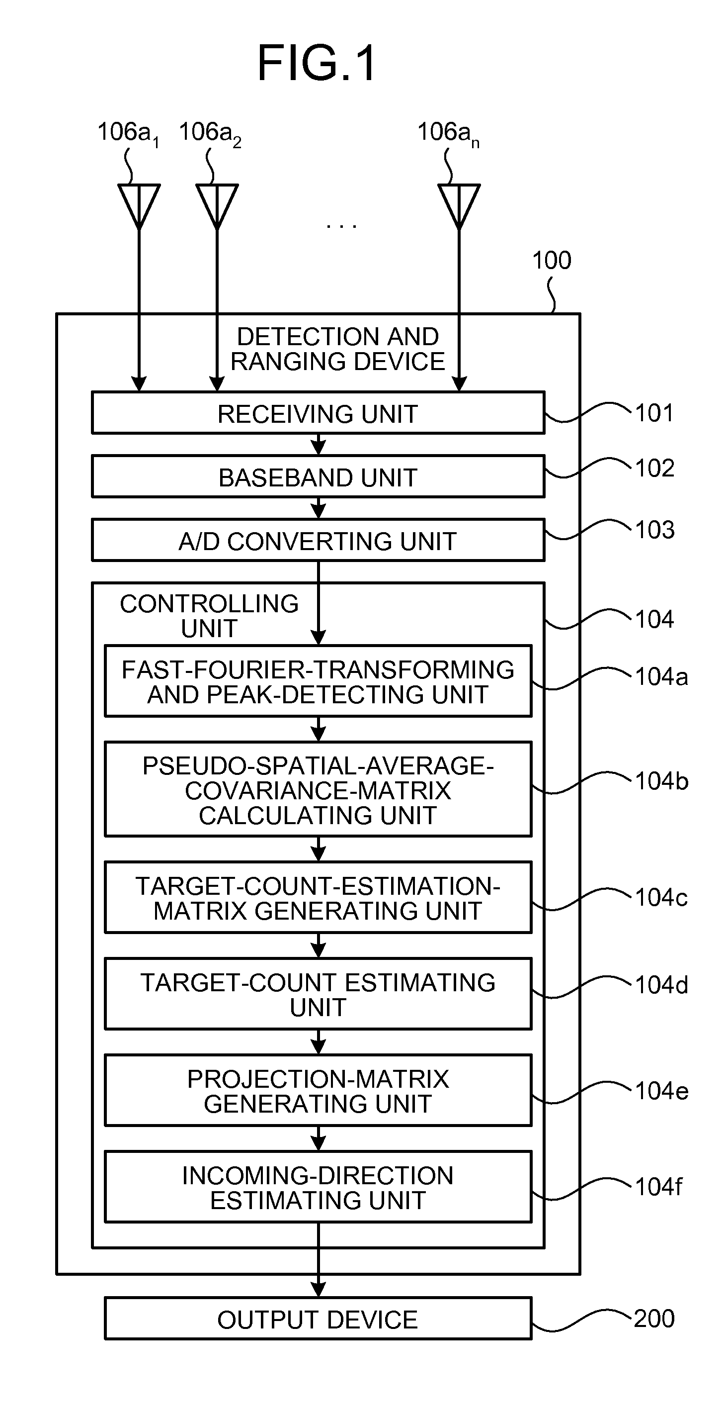
[0048]First, the configuration of the detection and ranging device according to an embodiment is explained. FIG. 1 is a functional block diagram of the configuration of the detection and ranging device according the embodiment. As depicted in FIG. 1, a detection and ranging device 100 according to the embodiment includes the sensor elements 106a1 to 106an equally spaced apart from each other so that a distance between adjacent sensor elements is d, a receiving unit 101 connected to the sensor elements 106a1 to 106an, a baseband unit 102, an analog / digital (A / D) converting unit 103, and a controlling unit 104.

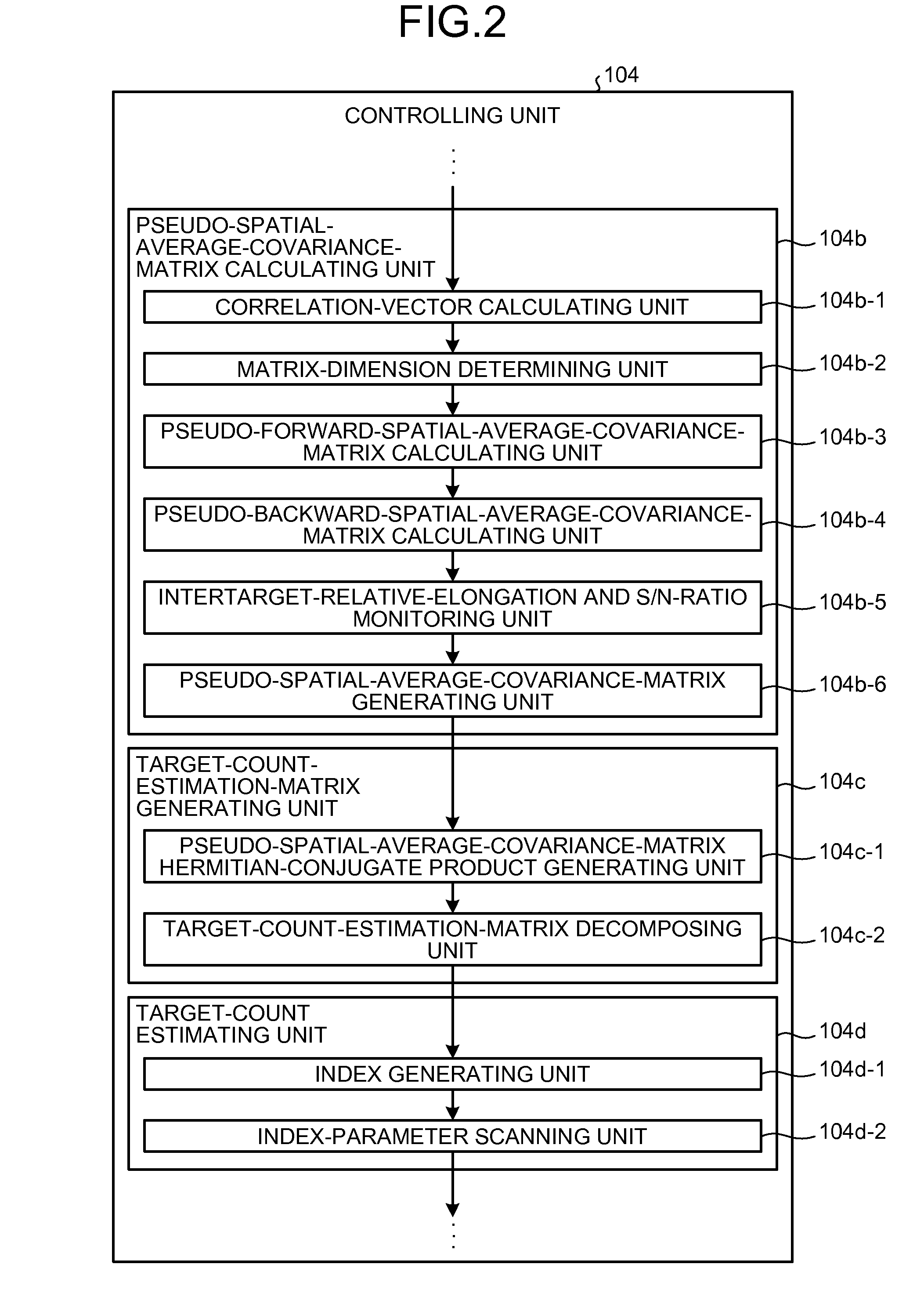
[0049]The controlling unit 104 includes a fast-Fourier-transforming and peak-detecting unit 104a, a pseudo-spatial-average-covariance-matrix calculating unit 104b, a target-count-estimatio...


PUM


Abstract

A pseudo-spatial-average-covariance-matrix generating unit selects, from matrixes Rf1, Rf2, Rb1 and Rb2, one appropriate matrix or two or more appropriate matrixes for combination to generate a pseudo-spatial-average-covariance matrix R. A pseudo-spatial-average-covariance-matrix Hermitian-conjugate product generating unit generates a target-count-estimation matrix RRH. A target-count-estimation-matrix decomposing unit performs LU decomposition on RRH into a lower triangular matrix L and an upper triangular matrix U. An index generating unit generates an index using elements of the upper triangular matrix U. An index-parameter scanning unit estimates a target count by using the index generated by the index generating unit.

Description


Claims


Application Information

Patent Timeline
Owner FUJITSU LTD
Why Eureka
Try Eureka