Illumination apparatus

Active Publication Date: 2009-09-10
IND TECH RES INST
View PDF14 Cites 49 Cited by
  • Summary
  • Abstract
  • Description
  • Claims
  • Application Information

AI Technical Summary

Benefits of technology

[0009]Accordingly, the present invention is directed to an illumination apparatus. A lens package structure with various curvatures is adopted to form illumination ranges at different angles, and also narrow down the light illumination angle in the moving direction of the vehicle so as to prevent the light from the street lighting being directly irradiated into the visual field of the driver. Thereby, the glare problem can be eliminated.
[0011]In the present illumination apparatus, a lens package structure with various curvatures is combined with a light-emitting unit, so as to reduce the weight and volume of the illumination apparatus. Moreover, the lens package structure with various curvatures can be used to provide illumination ranges at different angles.

Problems solved by technology

However, seen from the illumination design point, the street lighting and the speed of the vehicle are the most critical.
As a result, the driver may easily feel an eye fatigue and will be in a dangerous situation.
If a large range of the road surface is to be lighted, plenty of lights will be projected on places outside the road surface to cause light waste and pollution.
Further, if the irradiated light form is to be adjusted by a reflector, a deeper reflector is required to get a satisfactory result, but the weight and size of the lamp will be huge.

Method used


Image

  • Illumination apparatus
  • Illumination apparatus
  • Illumination apparatus

Examples


first embodiment

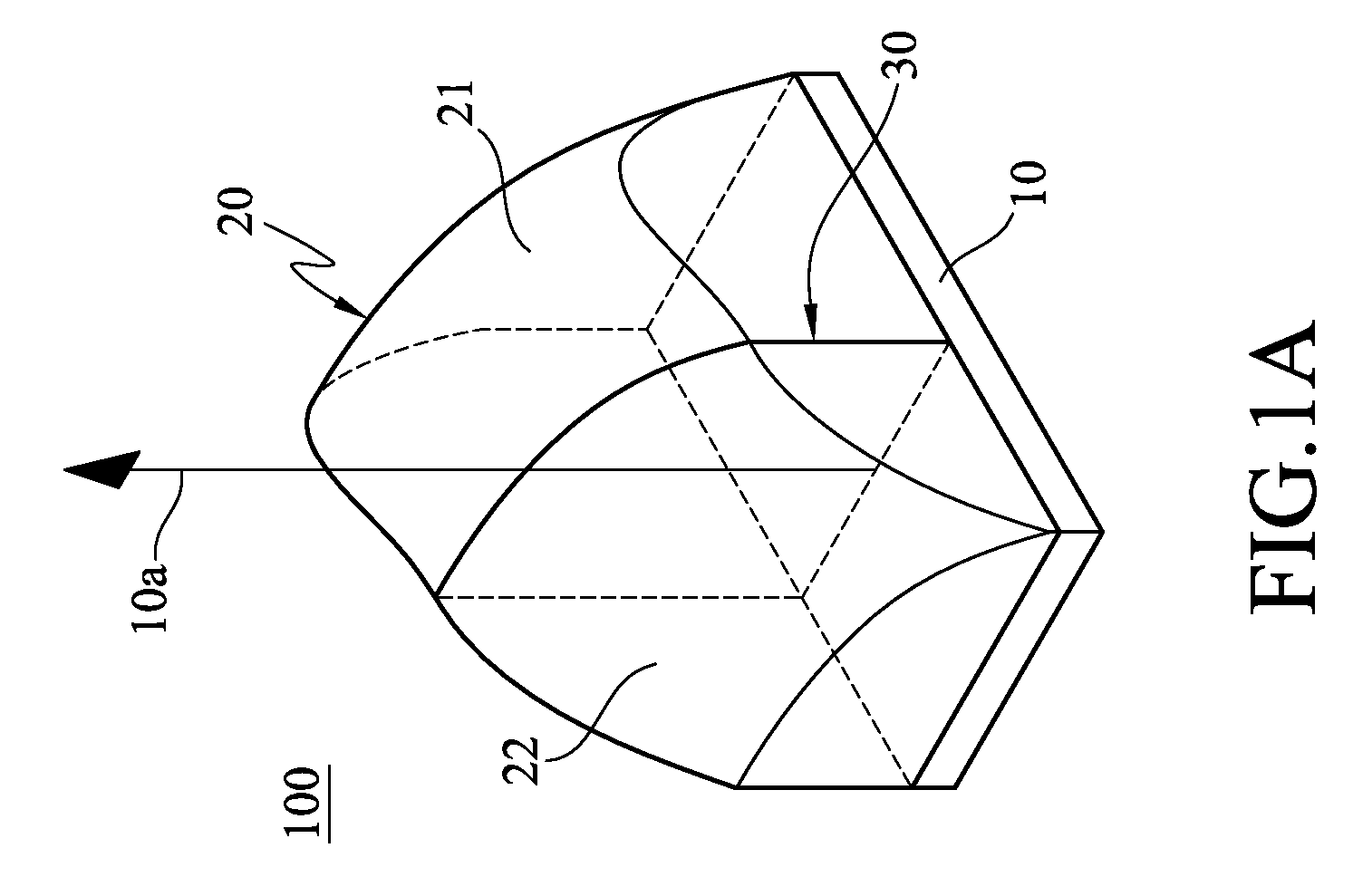
[0027]Referring to FIG. 1A, a schematic three-dimensional view of the present invention is shown. In FIG. 1A, a illumination apparatus 100 of the present invention includes a light-emitting unit 10 and a lens module 20. The lens module 20 has a first curved surface 21 and a second curved surface 22 separated from each other by a first borderline 30.

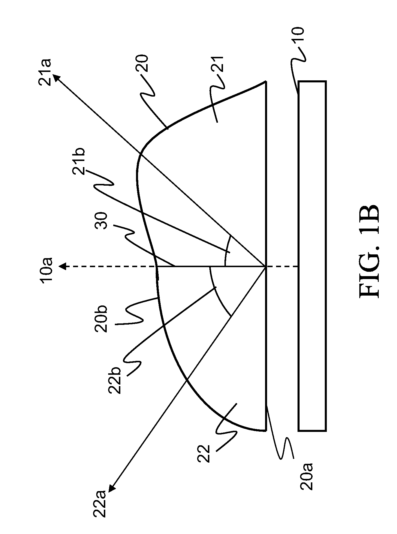
[0028]Referring to FIG. 1B, a side view of the first embodiment of the present invention is shown. In FIG. 1B, the light-emitting unit 10 and the lens module 20 are separated for the ease of illustration and may also be joined together upon actual requirements. The light-emitting unit 10 is disposed on one side of the lens module 20, and those skilled in the art can also dispose the light-emitting unit 10 in the lens module 20, i.e., the lens module 20 wraps the light-emitting unit 10. The light-emitting unit 10 is used for generating a plurality of lights, and has a light exit axis 10a representing the main traveling direction of the lig...

second embodiment

[0030]Referring to FIG. 2A, a schematic three-dimensional view of the present invention is shown. In FIG. 2A, the illumination apparatus 100 of the present invention includes a light-emitting unit 10 and a lens module 20. The lens module 20 has a first curved surface 21, a second curved surface 22, a third curved surface 23, and a fourth curved surface 24. The first curved surface 21 is separated from the second curved surface 22 by a first borderline 30, and the third curved surface 23 is separated from the fourth curved surface 24 by the first borderline 30. The first curved surface 21 is separated from the third curved surface 23 by a second borderline 31, and the second curved surface 22 is separated from the fourth curved surface 24 by the second borderline 31. The first borderline 30 and the second borderline 31 are crossed, and the first curved surface 21, the second curved surface 22, the third curved surface 23, and the fourth curved surface 24 with different curvatures are...

third embodiment

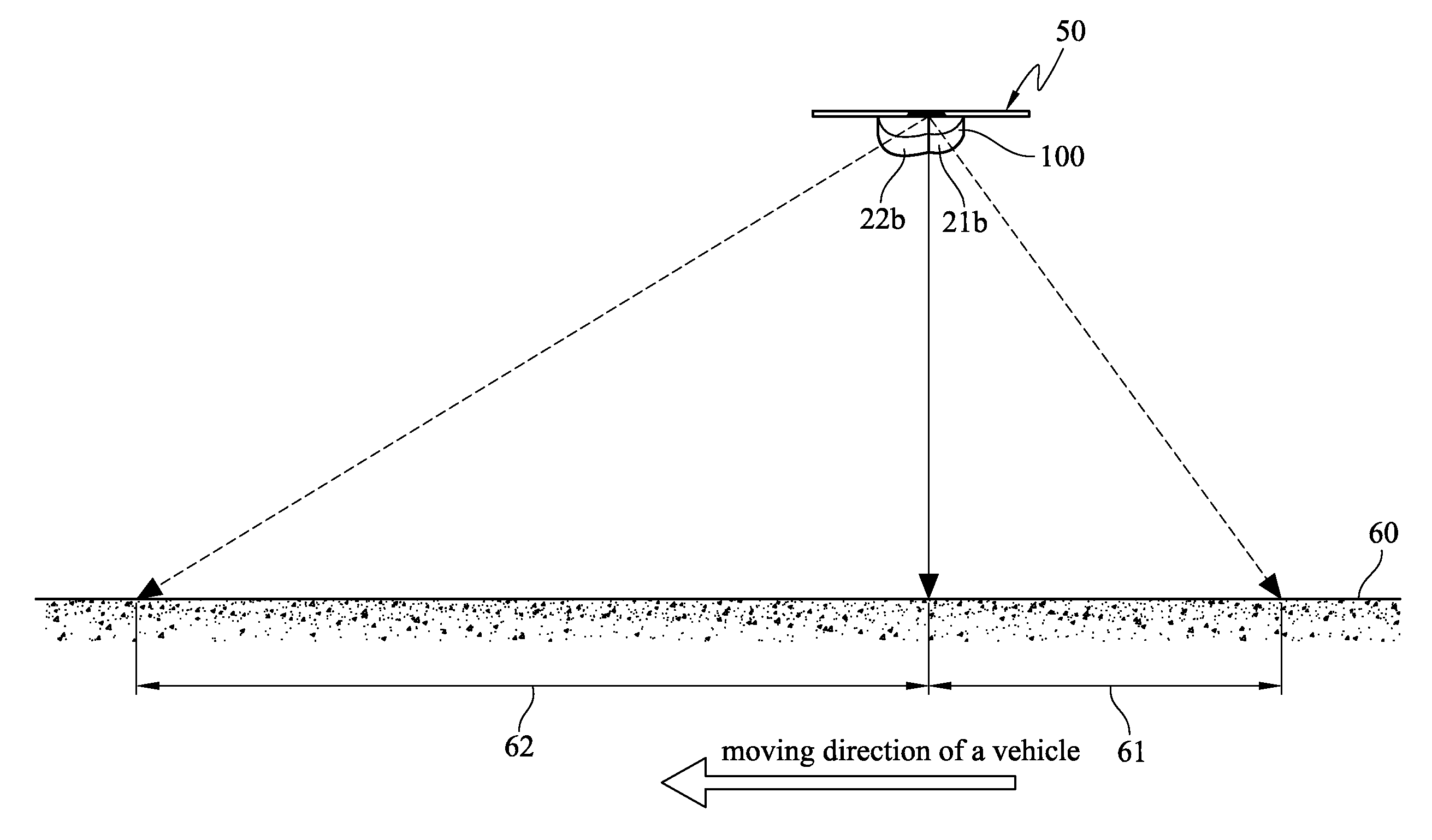
[0038]Referring to FIG. 4A, a schematic view of the present invention is shown. In FIG. 4A, a plurality of illumination apparatus 100 is mounted on a fixed lamppost 50 to enhance the luminance.


PUM


Abstract

An illumination apparatus including a light-emitting unit and a lens module is described. The light-emitting unit is used for generating a light and has a light exit axis. The lens module has a light exit surface with a plurality of curved surfaces. The lens module receives the light and outputs the light from the curved surfaces. Further, the curved surfaces have at least two curvatures, each for adjusting a illumination range of the light output from the corresponding curved surface.

Description

CROSS-REFERENCE TO RELATED APPLICATIONS[0001]This non-provisional application claims priority under 35 U.S.C. §119(a) on Patent Application No. 097108177 filed in Taiwan, R.O.C. on Mar. 7, 2008 the entire contents of which are hereby incorporated by reference.BACKGROUND OF THE INVENTION[0002]1. Field of Invention[0003]The present invention relates to an illumination apparatus, and more particularly to an asymmetrical illumination apparatus.[0004]2. Related Art[0005]The main purpose of street lighting is to enhance and guarantee night traffic safety. For driving, street lighting enables drivers to see the forward visual field more clearly, so as to take safety measures timely within an appropriate distance. This safety distance is closely related to the street lighting, the speed of the vehicle, the road condition, the performance of the vehicle, and the reaction capacity of the driver. However, seen from the illumination design point, the street lighting and the speed of the vehicle...

Claims


Application Information

Patent Timeline
IPC IPC(8): F21V5/00F21V3/00
CPCF21V5/08G02B3/10F21Y2101/02F21W2131/103F21Y2101/00F21Y2103/00F21Y2115/10
Inventor CHANG, HSUEN-CHIHHU, HUNG-LIEHHUANG, SHENG-PANCHEN, CHIU-LINGCHEN, CHEN-KUN
Owner IND TECH RES INST
Why Eureka
Try Eureka