
Radiation heat dissipation LED structure and the manufacturing method thereof

a technology of led and manufacturing method, which is applied in the direction of semiconductor/solid-state device manufacturing, electrical equipment, semiconductor devices, etc., can solve the problems of limiting the actual application, reducing the heat dissipation efficiency of the led structure. , to achieve the effect of reducing the working temperature of the led epitaxy layer, fast transfer of heat, and high heat dissipation efficiency

Inactive Publication Date: 2013-03-28
JINGDEZHEN FARED TECH
View PDF0 Cites 0 Cited by
  • Summary
  • Abstract
  • Description
  • Claims
  • Application Information

AI Technical Summary

Benefits of technology

The radiation heat dissipation film is made of metal and nonmetal and has a microscopic structure with crystals. It can efficiently transfer heat generated by LED epitaxy layers outwards through the base substrate by thermal radiation, reducing the working temperature of the LED layer and improving stability and lifetime. The conducting current in the LED layer can also increase, improving efficiency of light emitting. The film eliminates the need for leadframe and aluminum heat sink, reducing material and manufacturing costs. The LED structure is also lighter and smaller, expanding application scope and improving ease of use.

Problems solved by technology

However, one of the shortcomings in the prior arts is that the LED structure 1 may become considerably huge and heavy because the efficiency of heat dissipation depends on the effective surface area for heat dissipation if the heat is transferred primarily by thermal conduction.
This may limit the actual application.

Method used


Image

  • Radiation heat dissipation LED structure and the manufacturing method thereof
  • Radiation heat dissipation LED structure and the manufacturing method thereof
  • Radiation heat dissipation LED structure and the manufacturing method thereof

Examples


Embodiment Construction

[0016]The present invention may be embodied in various forms and the details of the preferred embodiments of the present invention will be described in the subsequent content with reference to the accompanying drawings. The drawings (not to scale) show and depict only the preferred embodiments of the invention and shall not be considered as limitations to the scope of the present invention. Modifications of the shape of the present invention shall too be considered to be within the spirit of the present invention.

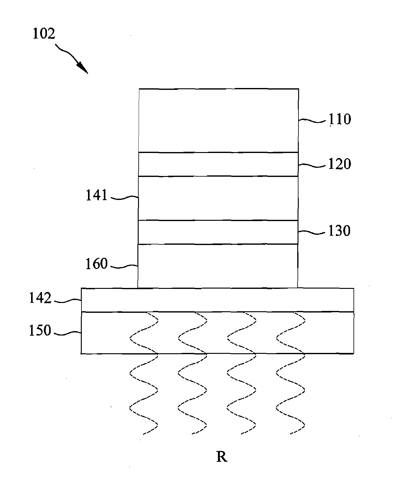
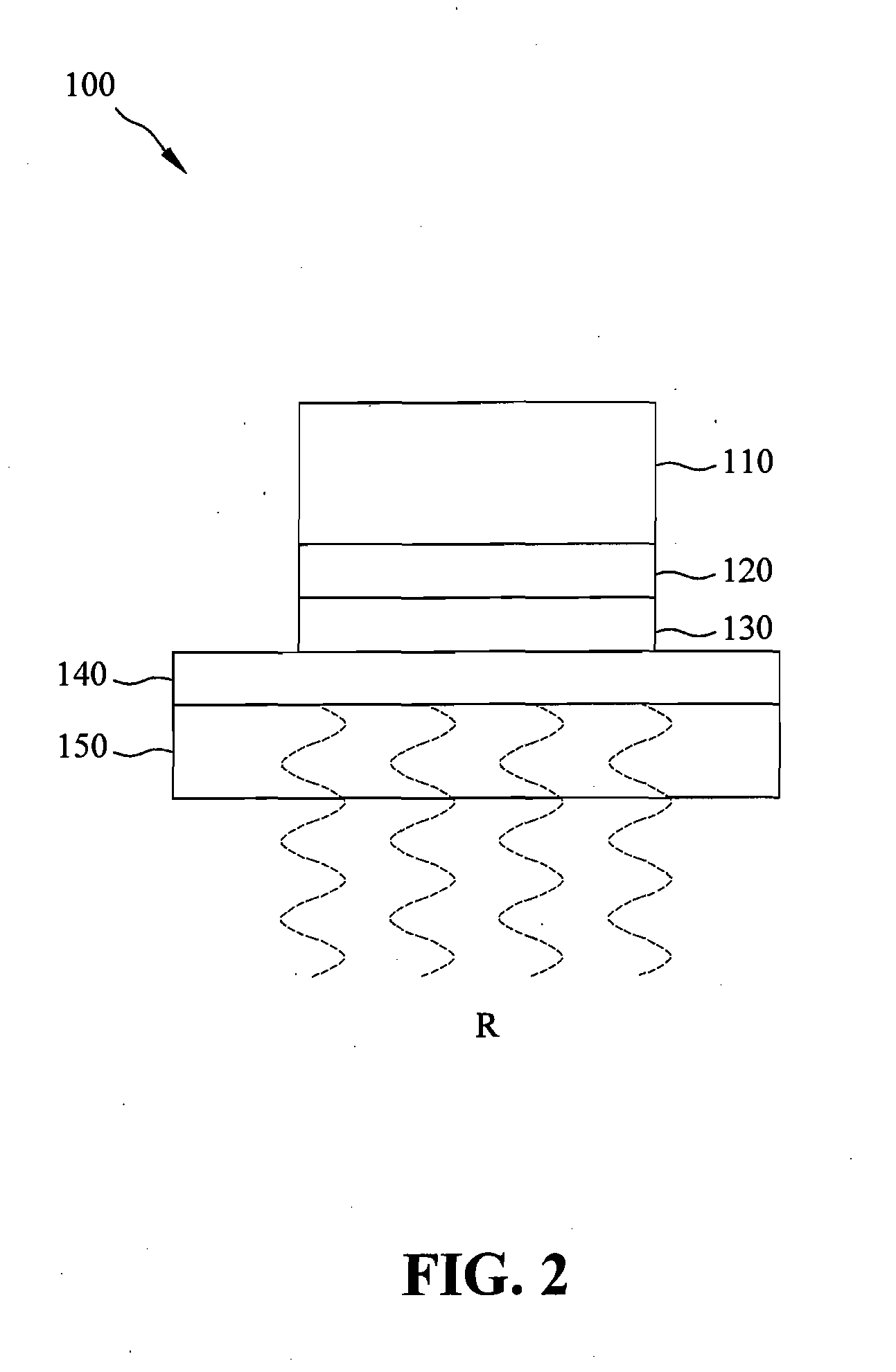
[0017]FIG. 2 illustrates the radiation heat dissipation LED structure according to one embodiment of the present invention. As shown in FIG. 2, the radiation heat dissipation LED structure 100 of the present invention includes an LED epitaxy layer 110, a sapphire substrate 120, a thermally conductive binding layer 130, a radiation heat dissipation film 140, a base substrate 150, at least one electrical connection line (not shown) and a package body (not shown). The LED epit...


PUM


Abstract

Disclosed are a radiation heat dissipation LED structure and a manufacturing method thereof. The radiation heat dissipation LED structure includes a sapphire substrate, an LED epitaxy layer, a base substrate, a radiation heat dissipation film, and a thermally conductive binding layer provided between the sapphire substrate and the radiation heat dissipation film to bind the sapphire substrate and the base substrate. The radiation heat dissipation film consists of a mixture of metal and nonmetal. The surface of the film has a microscopic structure with crystal, which has high efficiency of heat dissipation and can fast transfer the heat generated by the LED epitaxy layer outwards through the base substrate by thermal radiation. Therefore, the working temperature of the LED epitaxy layer is greatly reduced so as to improve the efficiency of light emitting and the lifetime.

Description

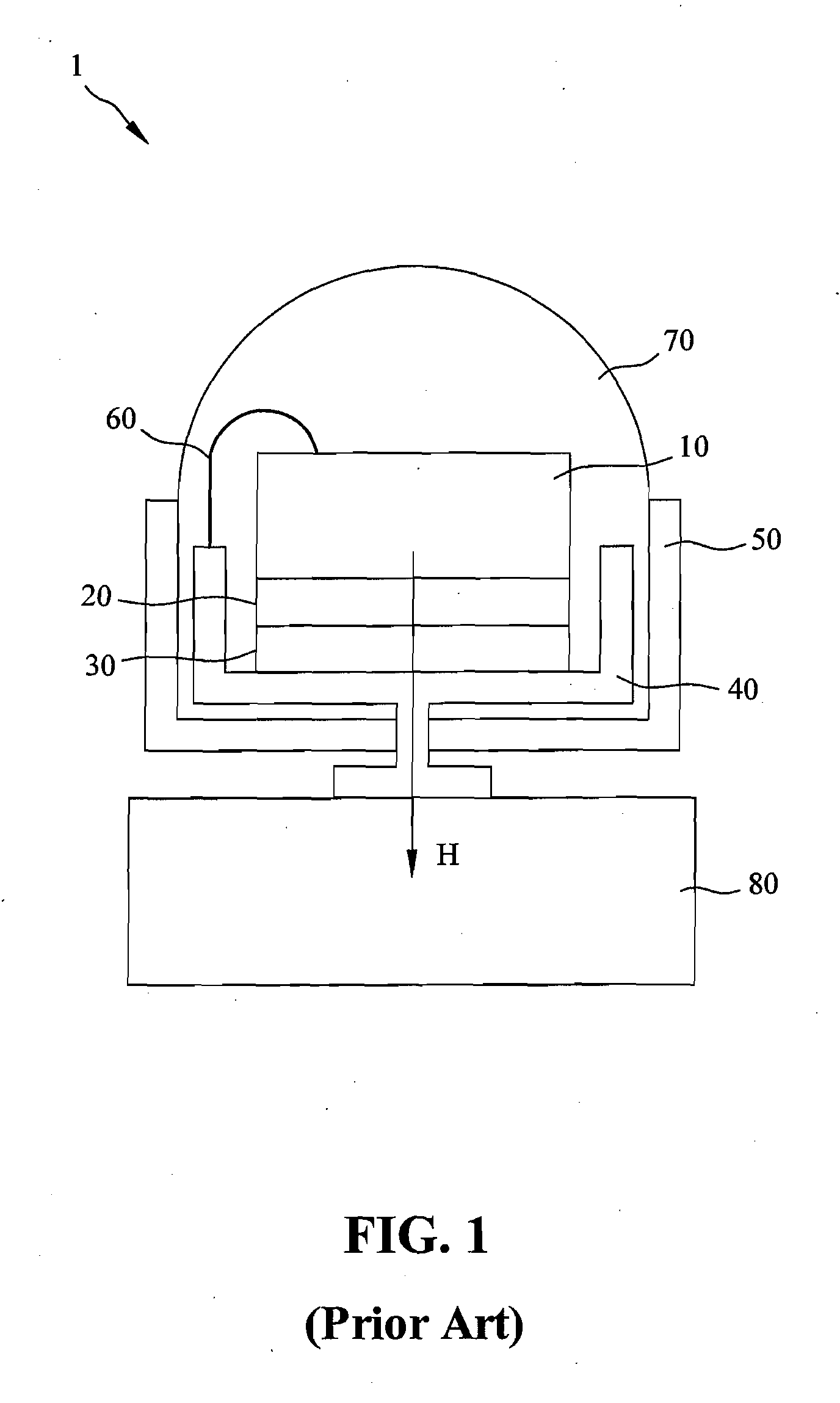
BACKGROUND OF THE INVENTION[0001]1. Field of the Invention[0002]The present invention generally relates to a radiation heat dissipation LED (light emitting diode) structure and a manufacturing method thereof, and more specifically to a radiation heat dissipation LED structure having a radiation heat dissipation film to enhance the cooling effect through thermal radiation.[0003]2. The Prior Arts[0004]Recently, LED has been widely applied to various fields due to the advantage in power saving and carbon reducing, and is also selected as one of the possible light sources to replace the traditional light bulb.[0005]As shown in FIG. 1, the LED structure 1 in the prior arts generally includes an LED chip 10, a sapphire substrate 20, a sliver paste 30, a leadframe 40, a base substrate 50, connection lines 60, a package body 70 and an aluminum heat sink 80. The LED chip 10 is formed on the sapphire substrate 20 and is bound with the leadframe 40 by the sliver paste 30. The base substrate 50...

Claims


Application Information

Patent Timeline
IPC IPC(8): H01L33/64H01L33/62
CPCH01L33/641H01L2224/48091H01L2224/48227H01L2224/73265H01L2924/00014
Inventor CHEN, JEONG-SHIUN
Owner JINGDEZHEN FARED TECH
Learn More