Fiber optic connector removal clips

Inactive Publication Date: 2009-09-10
MOLEX INC
View PDF12 Cites 49 Cited by
  • Summary
  • Abstract
  • Description
  • Claims
  • Application Information

AI Technical Summary

Benefits of technology

[0012]According to further aspects, objects or embodiments, the removal clip is economical and easy to produce and easy to u

Problems solved by technology

While removing fiber optic connectors with digital ease is an important consideration, it is u

Method used


Image

  • Fiber optic connector removal clips
  • Fiber optic connector removal clips
  • Fiber optic connector removal clips

Examples


second embodiment

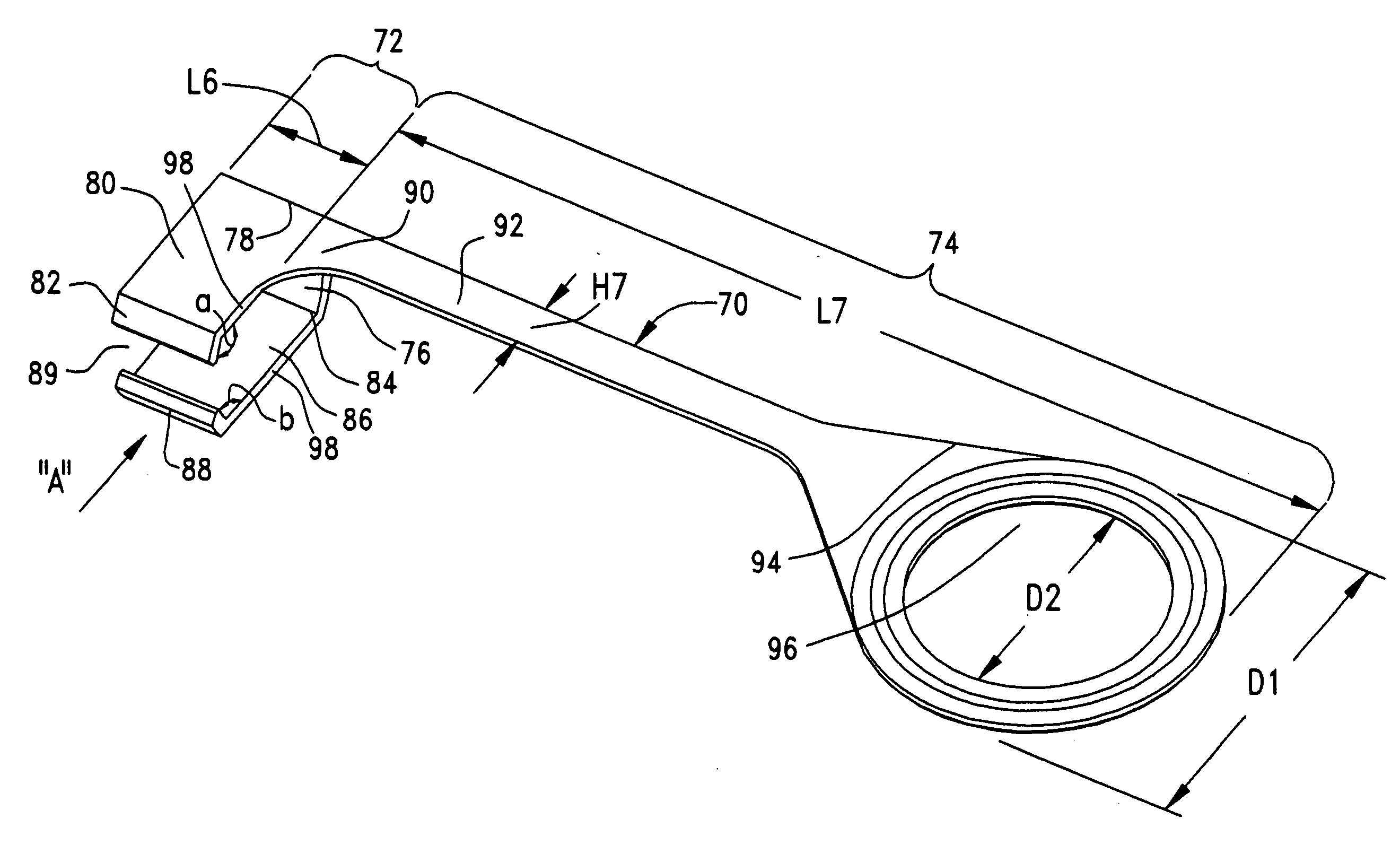
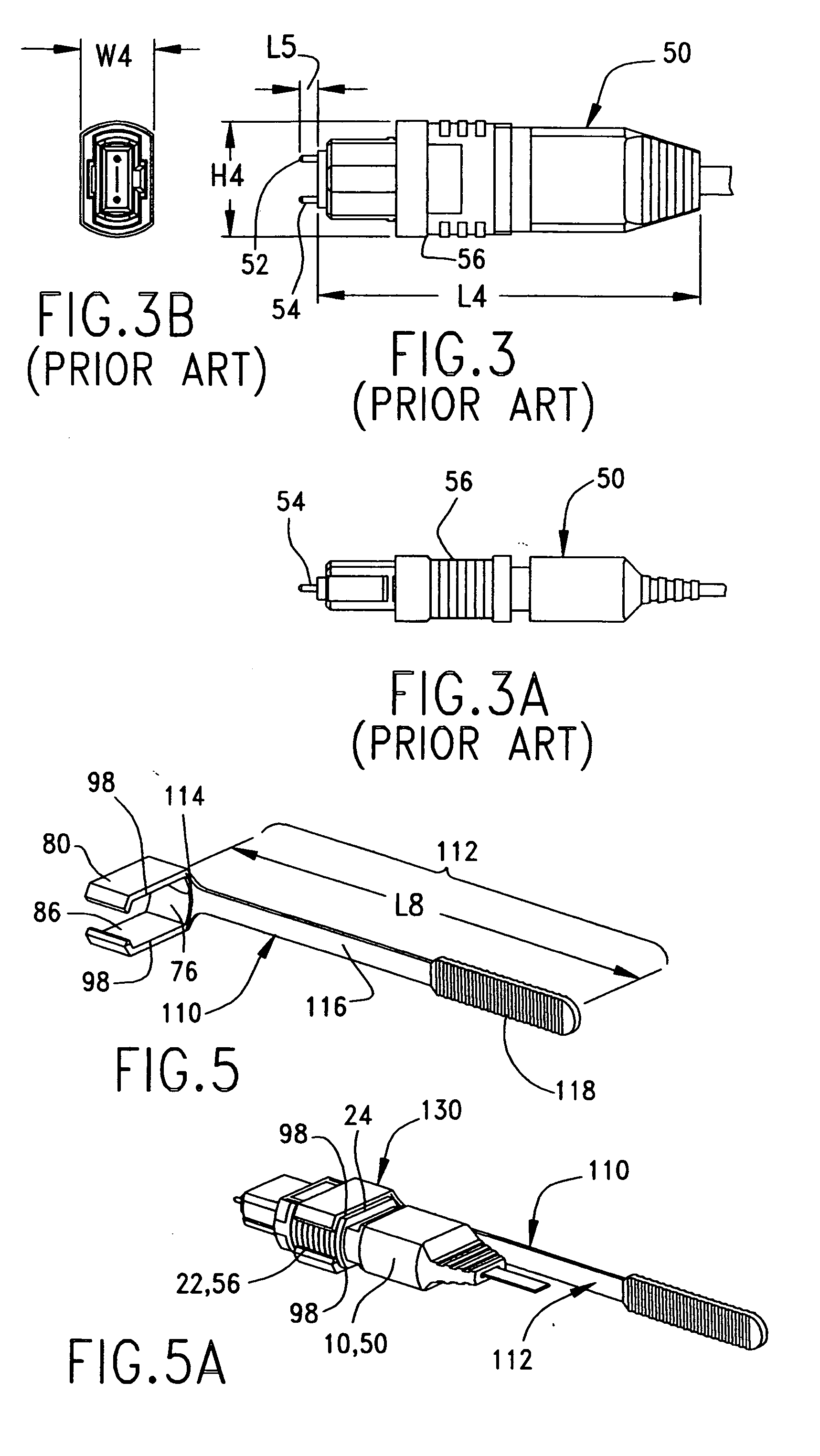
[0047]FIG. 5 illustrates a fiber optic connector removal clip or tool, generally shown as 110, that has a force transmitting portion generally shown as 112 with a length (L8) typically of about 70 mm. Force transmitting portion 112 includes a transition portion 114 that extends from the web 76 of engagement portion 72 in a direction considered axial and extends into force transmitting beam 116. Force transmitting portion 112 also includes at its proximal portion a linear handle 118 that extends from the force transmitting beam 116. It will be noted that, with this embodiment, the handle is generally perpendicular to the latch arms extending from the web 76, the handle 118 being centered with respect to the bight portion of the distally positioned engagement portion 72. This provides a relatively centered engagement between the rearwardly facing edge 98 of the engagement portion latch arm and the shoulder 24 of the connector.

[0048]FIG. 5A illustrates an embodiment of a clip-connector...

third embodiment

[0050]FIG. 7 illustrates a connector removal clip or tool generally shown as 150 with force transmitting section generally shown as 152 that is a projection extending from the web 76 in a direction considered generally axial to the latch arms 80, 88 of engagement portion 72, while being generally perpendicular to the connector when in use. Force transmitting section 152 is comprised of a projection portion 154 and terminal handle portion 156. Section 152 has length (L9) of about 3 mm, a width (W9) of about 6 mm, and a height (H9) of about 6 mm (FIG. 8A).

[0051]FIG. 7A shows an embodiment of a third clip-connector assembly generally shown as 160 that is comprised of the connector removal clip or tool 150 releasably attached to connector 10 or connector 50. Digital removal force can thus be more easily applied at terminal handle portion 156 and away from the congestion surrounding body sections of connectors. FIGS. 8 and 8A show third clip-connector assemblies 160 mounted to adapters 1...


PUM


Abstract

A removal clip is provided for disconnecting a fiber optic connector from an array of installed fiber optic connectors. The removal clip includes an engagement portion for engaging the connector and a force transmitting structure that allows digital removal force from a user to be applied at a distance from the connector. The engagement portion may be generally U-shaped and includes opposing latch arms configured to accommodate the body of a fiber optic connector. The latch arms permit the engagement portion to snap attach to the connector. The force transmitting structure may include a beam and a handle extending axially or radially from the gripping section. Also included is an assembly of a removal clip attached to a fiber optic connector.

Description

BACKGROUND OF THE INVENTION[0001]This present invention generally pertains to tools or removal devices for disconnecting fiber optic connectors. The removal device accommodates closely mounted fiber optic connectors in that a connector can be removed through the digital action of a user's hand without disrupting or dislodging surrounding connectors.DESCRIPTION OF BACKGROUND ART[0002]It is generally known that, from time to time, fiber optic connectors including standard connectors such as MPO connectors may be removed or unmated from another connector or from an adapter. For example, fiber optic connectors may need to be removed from an adapter or another connector for repair, replacement or to be used in a different configuration. These connectors are often mounted in tight configurations with little space between them to obtain high connector density. While removing fiber optic connectors with digital ease is an important consideration, it is undesirable to accomplish this to the ...

Claims


Application Information

Patent Timeline
IPC IPC(8): G02B6/00
CPCG02B6/3898G02B6/3897
Inventor BELENKIY, YURIYMARRAPODE, THOMAS R.
Owner MOLEX INC
Why Eureka
Try Eureka