Safety needle

a needle and safety technology, applied in the field of safe needles, can solve the problems of ever-present risk of litigation, significant risk of infection in the needle stick injury,

Active Publication Date: 2009-09-10
SALVUS TECH LIIMITED +1
View PDF52 Cites 92 Cited by
  • Summary
  • Abstract
  • Description
  • Claims
  • Application Information

AI Technical Summary

Benefits of technology

[0008]Briefly stated, the present invention is directed to a packing sleeve for use with a safety needle that automatically covers a tip of a needle following removal of the needle from a patient. The packing sleeve includes a generally hollow body having a longitudinal axis and a distal end and an open proximal end. The body surrounds at least a portion of the safety needle and has at least one track having an activation leg and a releasing leg. The at least one track is in sliding engagement with at least one member of the safety needle such that the motion of a portion of the safety needle relative to the body is dictated by a path the at least one member follows along the respective at least one track. The safety needle is in an initial position when the at least one member is proximate a first end of the activation leg and in an intermediate position when the at least one member is proximate a second end of the activation leg. The releasing leg extends from the second end of the activation leg and allows the at least one member to be slid toward and then removed from the proximal end of the body.
[0009]In another aspect, the invention is directed to a safety needle for automatically covering a tip of a needle following removal of the needle from a patient. The safety needle includes an injection device having an initial position and an intermediate position. A packing sleeve has a generally hollow body surrounding at least a portion of the injection device in the initial position and the intermediate position. The body is only removable from the injection device when the injection device is in the intermediate position.
[0010]In another aspect, the invention is directed to a safety needle for automatically covering a tip of a needle following removal of the needle from a patient. The safety needle comprises a hollow needle having a tip for injecting into the patient and a longitudinal axis. A hub is mounted to the needle and has an outer surface, a receiving end distal to the tip of the needle and an injection end proximal to the tip of the needle. The injection end has at least one recess. At least part of the outer surface of the hub tapers inwardly toward the injection end. A slidable sleeve has a mounting end distal to the tip of the needle and an injection end proximal to the tip of the needle. The tip of the needle is located inside the slidable sleeve in an extended position and the tip of the needle projects from the slidable sleeve in a retracted position. At least one projection having an enlarged distal width and a reduced proximal width extends radially inwardly from the mounting end and is slidably mounted to the hub between the receiving and injection ends of the hub in an initial position. The outer surface of the hub deflects the at least one projection and slidable sleeve outwardly in a radial direction as the slidable sleeve slides axially toward the receiving end of the hub. A displacement force urges the slidable sleeve from the initial position toward the retracted position generates a restoring force within the slidable sleeve. The restoring force urges the slidable sleeve to move toward the injection end of the needle hub and into the extended position upon removal of the displacement force. The at least one projection slides into and is retained within the at least one recess in the extended position.
[0011]In another aspect, the invention is directed to a safety needle for automatically covering a tip of a needle following removal of the needle from a patient. The safety needle comprises a hollow needle having a tip for injecting into the patient and a longitudinal axis. A hub is mounted to the needle and has an outer surface, a receiving end distal to the tip of the needle and an injection end proximal to the tip of the needle. At least part of the outer surface of the hub tapers inwardly toward the injection end. A slidable sleeve has a mounting end distal to the tip of the needle and an injection end proximal to the tip of the needle. The tip of the needle is located inside the slidable sleeve in an extended position and the tip of the needle projects from the slidable sleeve in a retracted position. The slidable sleeve is slidably mounted to the hub between the receiving and injection ends of the hub in an initial position. The outer surface of the hub deflects the slidable sleeve outwardly in a radial direction as the slidable sleeve slides axially toward the receiving end of the hub. The outer surface deflects the slidable sleeve in a radial direction as the slidable sleeve slides toward the receiving end of the hub. A displacement force urges the slidable sleeve from the initial position toward the retracted position generating a restoring force within the slidable sleeve. The restoring force urges the slidable sleeve to move toward the injection end of the needle hub and into the extended position upon removal of the displacement force. The indicator marking is covered by the slidable sleeve in the initial and retracted positions and visible in the extended position.
[0012]In another aspect, the invention is directed to a safety needle for automatically covering a tip of a needle following removal of the needle from a patient. The safety needle comprises a hollow needle having a tip for injecting into the patient and a longitudinal axis. A hub is mounted to the needle and has an outer surface, a receiving end distal to the tip of the needle and an injection end proximal to the tip of the needle. At least part of the outer surface of the hub tapers inwardly toward the injection end. The hub has at least one catch having a cammed surface. The outer surface of the hub proximate the at least one catch decreases in radial dimension moving circumferentially from the catch. A slidable sleeve has a mounting end distal to the tip of the needle and an injection end proximal to the tip of the needle. The tip of the needle is located inside the slidable sleeve in an extended position and the tip of the needle projects from the slidable sleeve in a retracted position. The slidable sleeve is slidably mounted to the hub between the receiving and injection ends of the hub in an initial position. The outer surface of the hub deflects the at least one projection and slidable sleeve outwardly in a radial direction as the slidable sleeve slides axially toward the receiving end of the hub. A displacement force urges the slidable sleeve against the cammed surface to twist the slidable sleeve relative to the hub and urges the slidable sleeve from the initial position toward the retracted position generating a restoring force within the slidable sleeve. The restoring force urges the slidable sleeve to move toward the injection end of the needle hub and into the extended position upon removal of the displacement force. The at least one projection slides into and is retained within the at least one recess in the extended position.
[0013]In another aspect, the invention is directed to a safety needle for automatically covering a tip of a needle following removal of the needle from a patient. The safety needle comprises a hollow needle having a tip for injecting into the patient and a longitudinal axis. A hub is mounted to the needle and has an outer surface, a receiving end distal to the tip of the needle and an injection end proximal to the tip of the needle. The injection end has at least one recess. At least part of the outer surface of the hub tapers inwardly toward the injection end. A slidable sleeve has a mounting end distal to the tip of the needle and an injection end proximal to the tip of the needle. The injection end has a needle opening and an axially extending interior ridge proximate the needle opening. The tip of the needle being located inside the slidable sleeve in an extended position and the tip of the needle projecting from the slidable sleeve in a retracted position. At least one projection extending inwardly from the slidable sleeve is slidably mounted to the hub between the receiving and injection ends of the hub in an initial position. The outer surface of the hub deflects the at least one projection and slidable sleeve outwardly in a radial direction as the slidable sleeve slides axially toward the receiving end of the hub. A displacement force urges the slidable sleeve from the initial position toward the retracted position generating a restoring force within the slidable sleeve. The restoring force urges the slidable sleeve to move toward the injection end of the needle hub and into the extended position upon removal of the displacement force. The at least one projection slides into and is retained within the at least one recess in the extended position. Displacing the slidable sleeve radially in the extended position causes the tip of the needle to extend into the ridge of the slidable sleeve.

Problems solved by technology

Needle stick injuries carry a significant risk of spreading infection, such as HIV and hepatitis, and are commonplace among healthcare workers.
Other countries are following and, even without legislation, the ever-present risk of litigation has alerted pharmaceutical companies and health authorities to seek suitable safe devices.

Method used


Image

  • Safety needle
  • Safety needle
  • Safety needle

Examples


Embodiment Construction

[0055]Certain terminology is used in the following description for convenience only and is not limiting. The words “right”, “left”, “lower” and “upper” designate directions in the drawings to which reference is made. The words “inwardly” and “outwardly” refer to directions toward and away from, respectively, the geometric center of the safety needle, packing sleeve and designated parts thereof. Unless specifically set forth herein, the terms “a”, “an” and “the” are not limited to one element but instead should be read as meaning “at least one”. The terminology includes the words noted above, derivatives thereof and words of similar import.

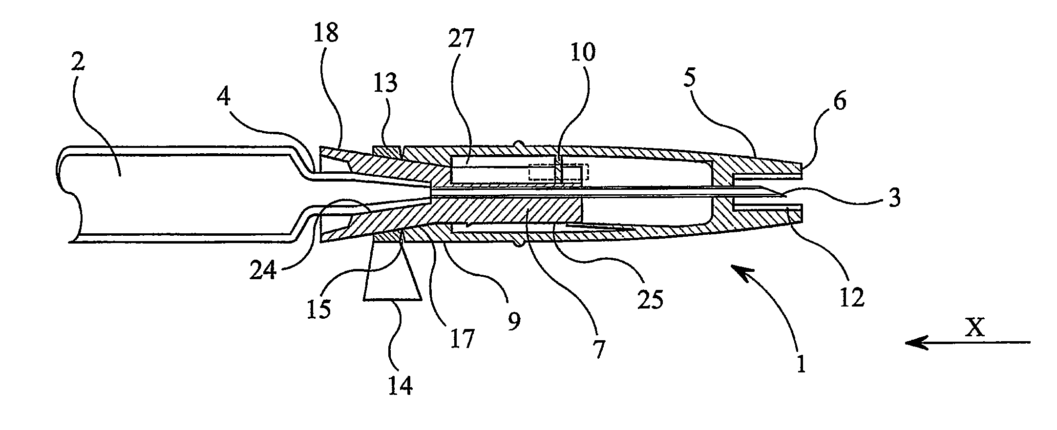
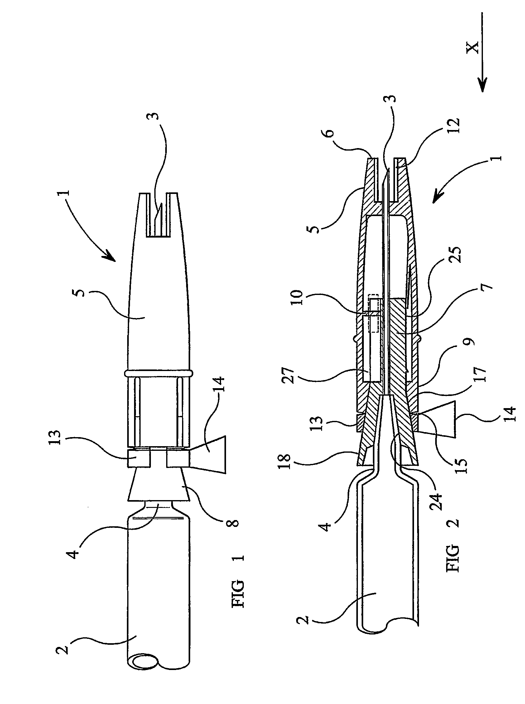
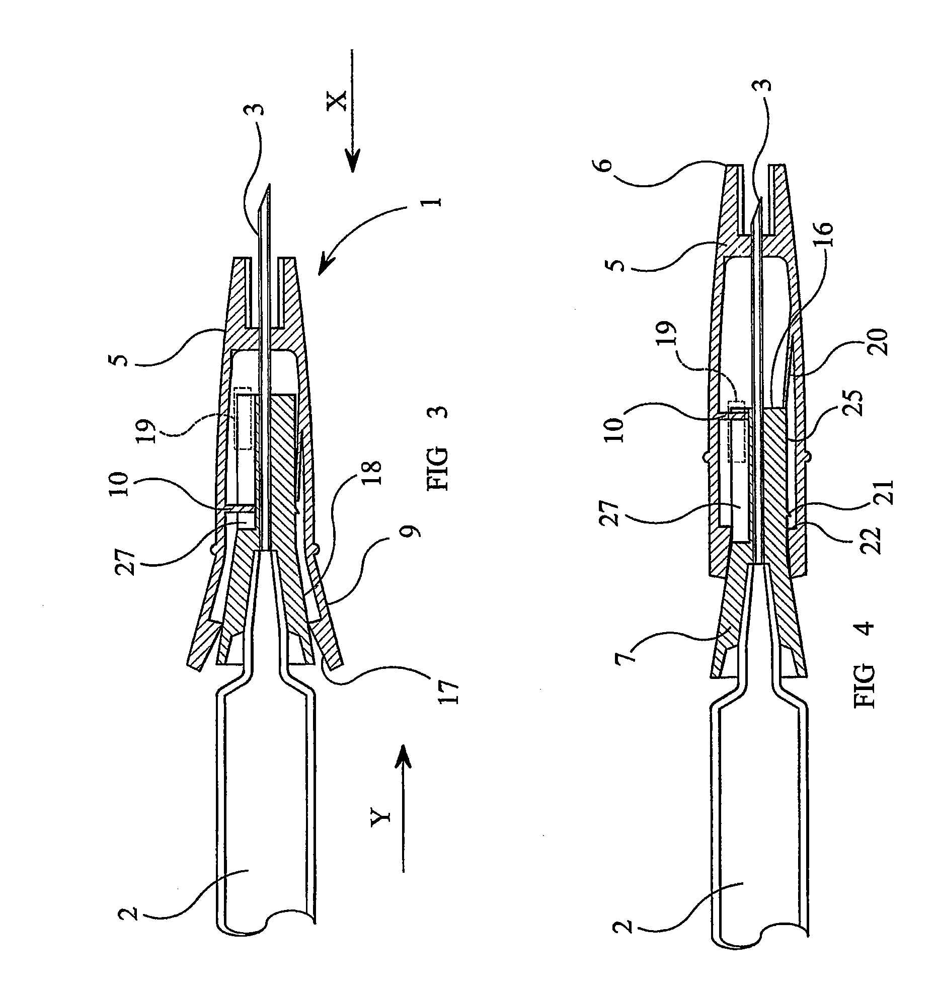
[0056]Referring to the drawings, wherein like numeral indicates like elements throughout, there is shown various embodiments of a safety needle 1 and corresponding covers or packing sleeves 35, 135, 235. FIGS. 1-8 exemplify a safety needle 1 for preventing needle stick injuries which is suitable for use with the packing sleeve 35 of the present inv...


PUM


Abstract

A packing sleeve for use with a safety needle that automatically covers a tip of a needle following removal of the needle from a patient includes a generally hollow body having a longitudinal axis and a distal end and an open proximal end. The body surrounds at least a portion of the safety needle and has at least one track having an activation leg and a releasing leg. The at least one track is in sliding engagement with at least one member of the safety needle such that the motion of a portion of the safety needle relative to the body is dictated by a path the at least one member follows along the respective at least one track. The safety needle is in an initial position when the at least one member is proximate a first end of the activation leg and in an intermediate position when the at least one member is proximate a second end of the activation leg. The releasing leg extends from the second end of the activation leg and allows the at least one member to be slid toward and then removed from the proximal end of the body.

Description

CROSS-REFERENCE TO RELATED APPLICATIONS[0001]This application is a Continuation-In-Part application of U.S. patent application Ser. No. 11 / 815,475 filed Aug. 3, 2007 which is a Section 371 of International Application No. PCT / GB2005 / 000357, filed Feb. 3, 2005, which was published in the English language on Aug. 10, 2006, under International Publication No. WO 2006 / 082350 A1 and the disclosures of each of which are incorporated herein by reference.BACKGROUND OF THE INVENTION[0002]This invention relates to a safety needle, particularly a safety needle for automatically covering a needle following removal of the needle from a patient and a packing sleeve for setting the safety needle in a ready-to-use configuration by the act of removing the packing sleeve.[0003]Needle stick injuries carry a significant risk of spreading infection, such as HIV and hepatitis, and are commonplace among healthcare workers. The United States of America has led the way in introducing legislation that oblige...

Claims


Application Information

Patent Timeline
Patent Type & Authority Applications(United States)
IPC IPC(8): A61M5/32
CPCA61M5/002A61M5/326A61M5/3272A61M2005/3268A61M2005/3247A61M2005/3267A61M5/5086
Inventor EMMOTT, DOUGLAS ARTHURNORTON, PAULLICENCE, ANTHONYWESTON, TERENCE EDWARDEATON, ANTHONY L.
Owner SALVUS TECH LIIMITED
Why Eureka
Try Eureka