
Joint Fixation System For the Hand

a technology for fixing systems and hands, applied in the field of surgical fixation devices for interphalangeal joint fusion and metacarpal phalangeal joint fusion, can solve problems such as difficult to precisely control the angle, pain in joints, and cases that cannot be treated with joint replacement, and achieve the effect of greater precision

Inactive Publication Date: 2009-09-10
MAYO FOUND FOR MEDICAL EDUCATION & RES
View PDF10 Cites 29 Cited by
  • Summary
  • Abstract
  • Description
  • Claims
  • Application Information

AI Technical Summary

Benefits of technology

The invention provides surgical methods and devices for fusing interphalangeal and metacarpal phalangeal joints with greater precision. It also includes a joint fixation plate that can be used in cases where a prosthesis needs to be removed due to infection or other reasons. The kit includes joint fixation plates, screws, and a drill guide for drilling pilot holes in each bone for receiving screws. Overall, the invention improves the accuracy and reliability of joint fusion procedures.

Problems solved by technology

The technical problem addressed in this patent is the need for an improved device for the surgical fixation of hand joints, specifically interphalangeal and metacarpal phalangeal joints, that provides greater precision in achieving a desired fused joint position. Current methods for achieving joint fusion can result in non-union of the fusion site, pain, and limited function of the hand. The patent seeks to address this problem by providing a more precise surgical device for achieving a desired fused joint position.

Method used


Image

  • Joint Fixation System For the Hand
  • Joint Fixation System For the Hand
  • Joint Fixation System For the Hand

Examples


Embodiment Construction

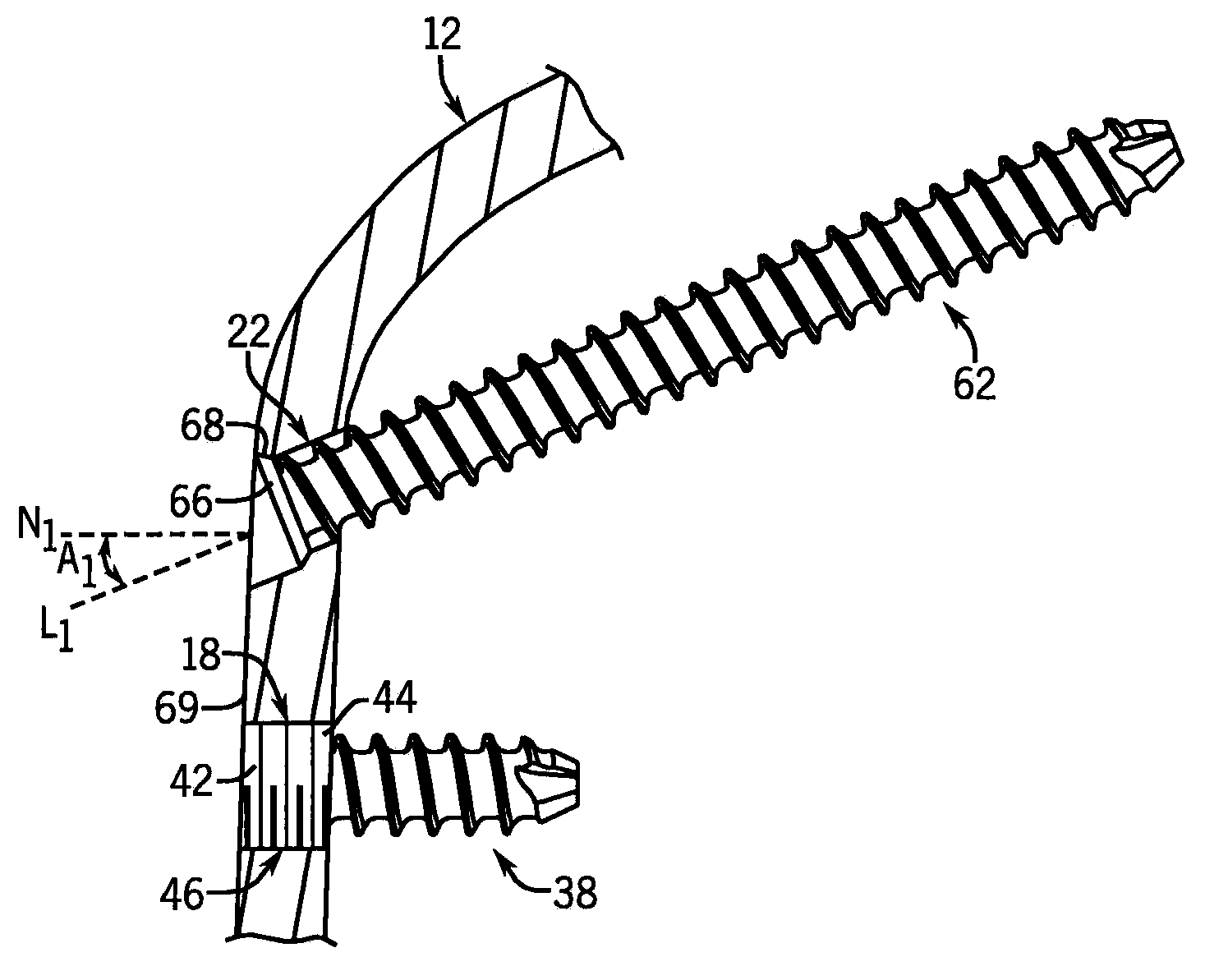
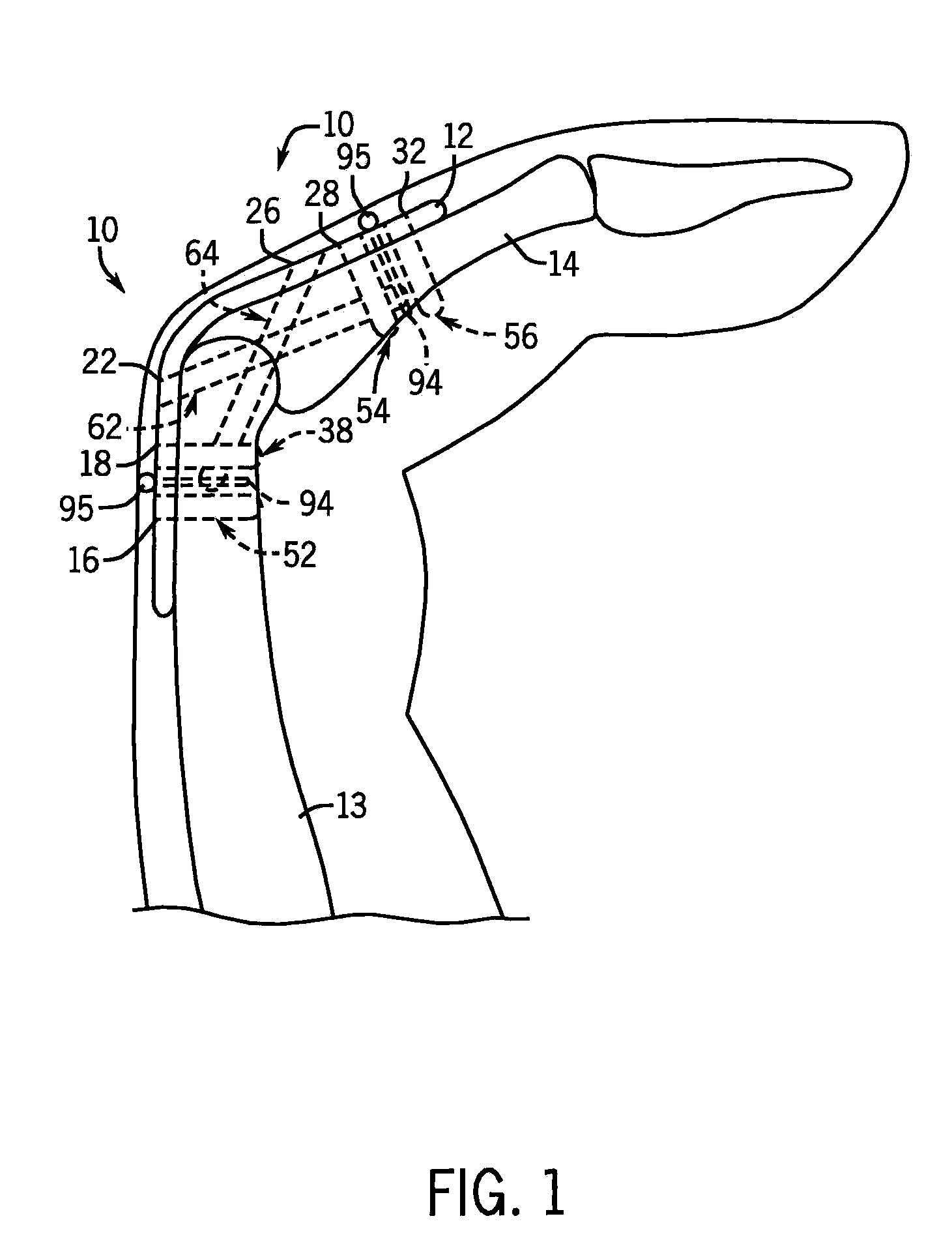
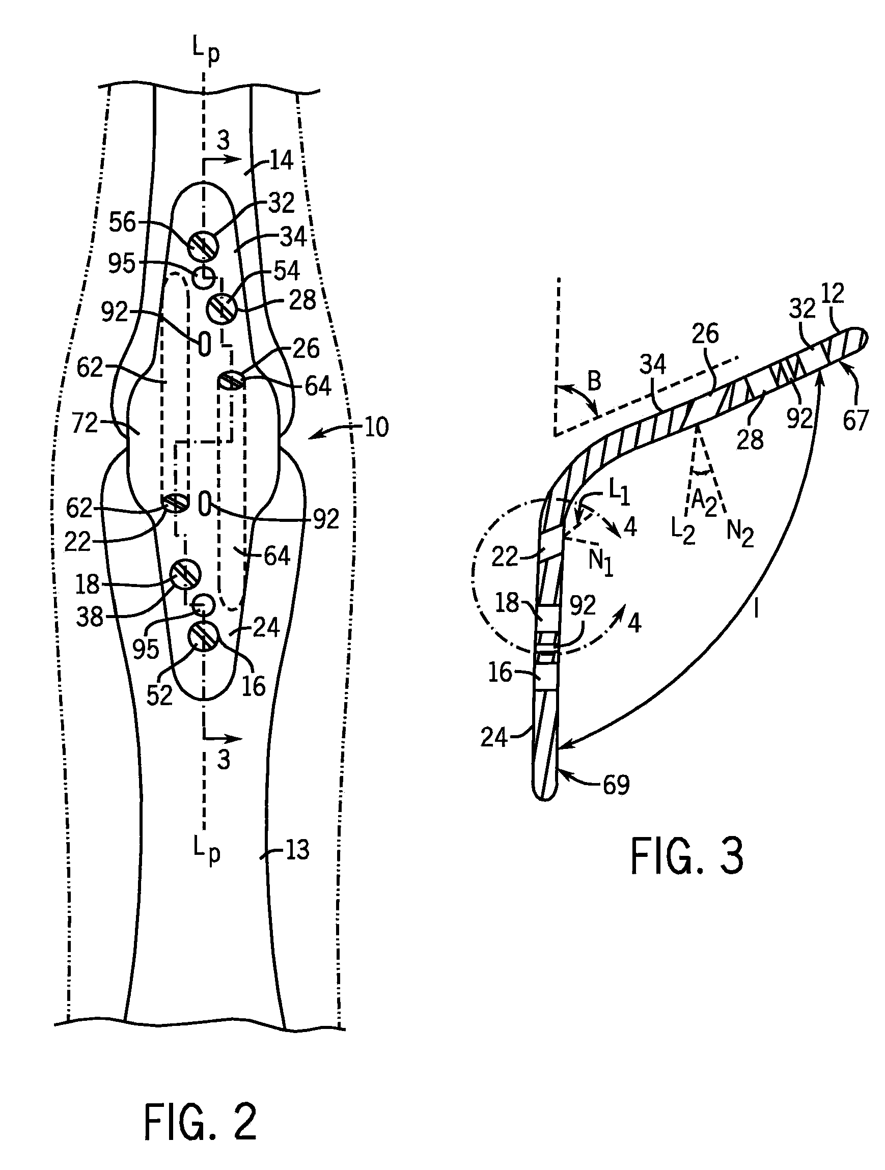
[0040]Looking first at FIGS. 1 to 4, there is shown one example embodiment of a joint fixation system 10 according to the invention. While the joint fixation system 10 is shown fixed on the proximal interphalangeal (PIP) joint of the left index finger, other embodiments of the invention can be used for any proximal interphalangeal (PIP) joint in the other fingers, a metacarpal phalangeal (MCP) joint in any finger, an interphalangeal (IP) joint in the thumb, or a metacarpal phalangeal (MCP) joint in the thumb.

[0041]The joint fixation system 10 includes a joint fixation plate 12. The surgical approach for the joint fixation system 10 can be dorsally for the IP, PIP and MCP joints. A cannulated cup and cone reamer system can be used to create matched mating surfaces for fusion of the opposed bone surfaces of the joint. Example reamer systems include: (1) the Small Joint Reamer available from Acumed, Hillsboro Oreg., USA; and (2) the Hallu®-Ream reamer system available from Integra Life...


PUM


Abstract

A joint fixation system particularly useful for joints of the hand is disclosed. The joint fixation system includes a joint fixation plate having a distal section, a proximal section, and an intermediate section connecting the distal section and the proximal section. The distal section includes a distal section screw hole, and the proximal section includes a proximal section screw hole. The joint fixation plate is pre-bent such that the distal section and the proximal section form an included angle of less than 180 degrees. The joint fixation system includes a first screw dimensioned to engage an inner surface of the distal section screw hole, and a second screw dimensioned to engage an inner surface of the proximal section screw hole. The first screw is angulated proximally when inserted in the distal screw hole, and the second screw is angulated distally when inserted in the proximal screw hole.

Description


Claims


Application Information

Patent Timeline
Owner MAYO FOUND FOR MEDICAL EDUCATION & RES
Learn More