Edge-Matched Articular Implant

a technology of articular implants and implants, applied in the field of orthopaedic systems, can solve problems such as the potential for interference with adjacent soft tissues and ligaments

Inactive Publication Date: 2009-09-10
CONFORMIS
View PDF202 Cites 114 Cited by
  • Summary
  • Abstract
  • Description
  • Claims
  • Application Information

AI Technical Summary

Benefits of technology

[0005]One embodiment is an implant configured to be fit into a cut portion of bone of a patient. The implant can include a substantially flat or substantially tray-shaped or dome-shaped body having an inferior surface, a superior surface, and an outer peripheral edge extendi

Problems solved by technology

Alternatively, in select cases, the implant may overhang with the p

Method used


Image

  • Edge-Matched Articular Implant
  • Edge-Matched Articular Implant
  • Edge-Matched Articular Implant

Examples


Embodiment Construction

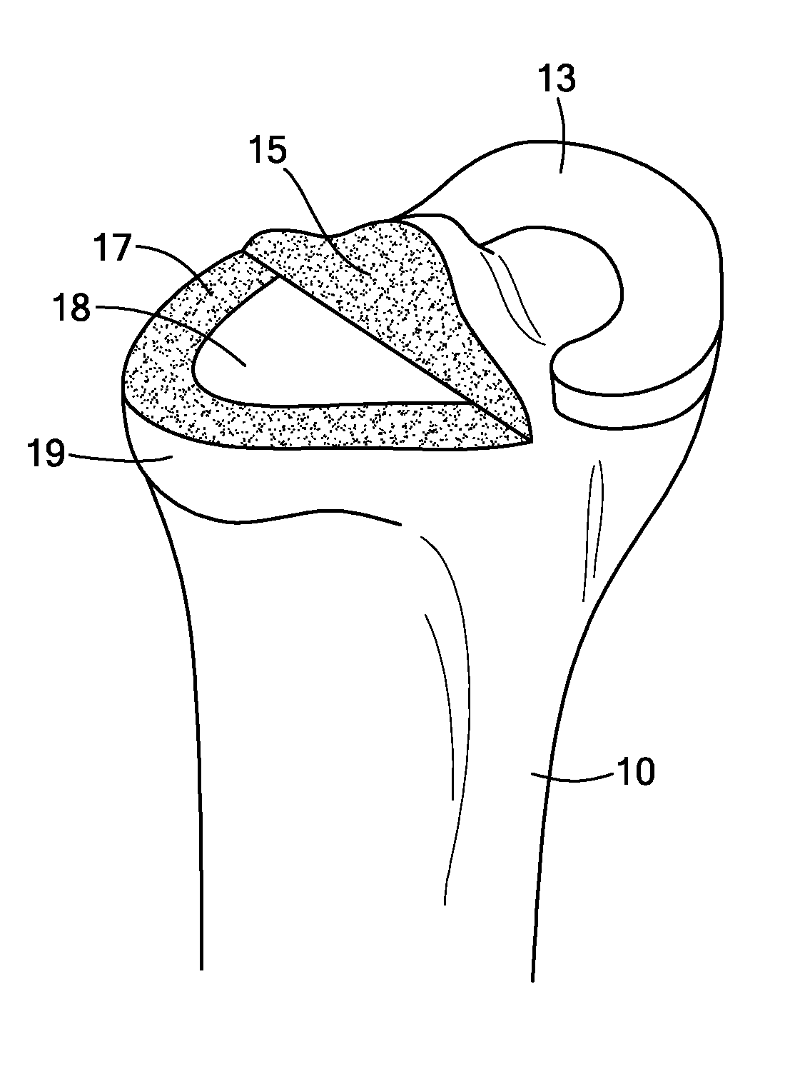
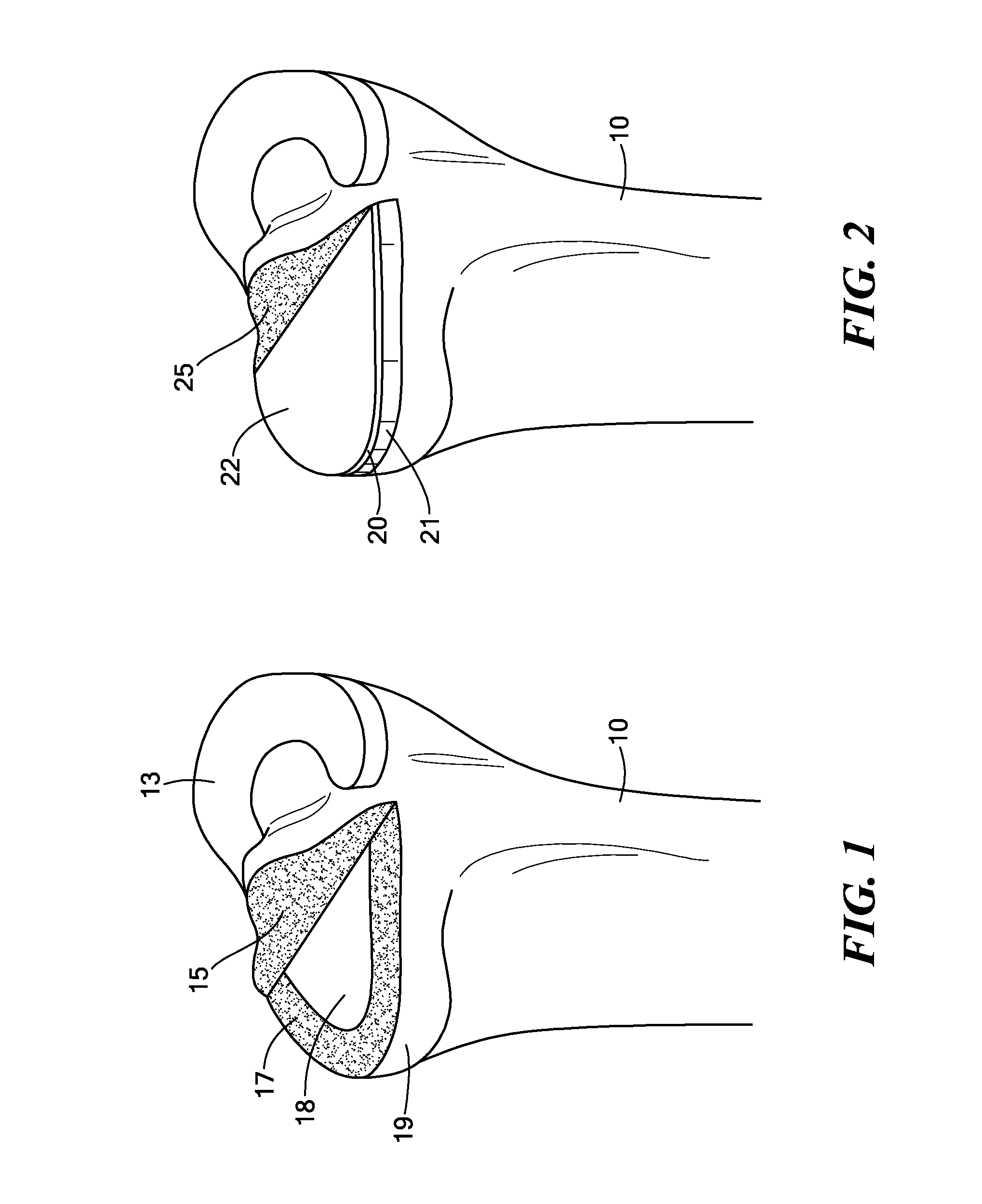
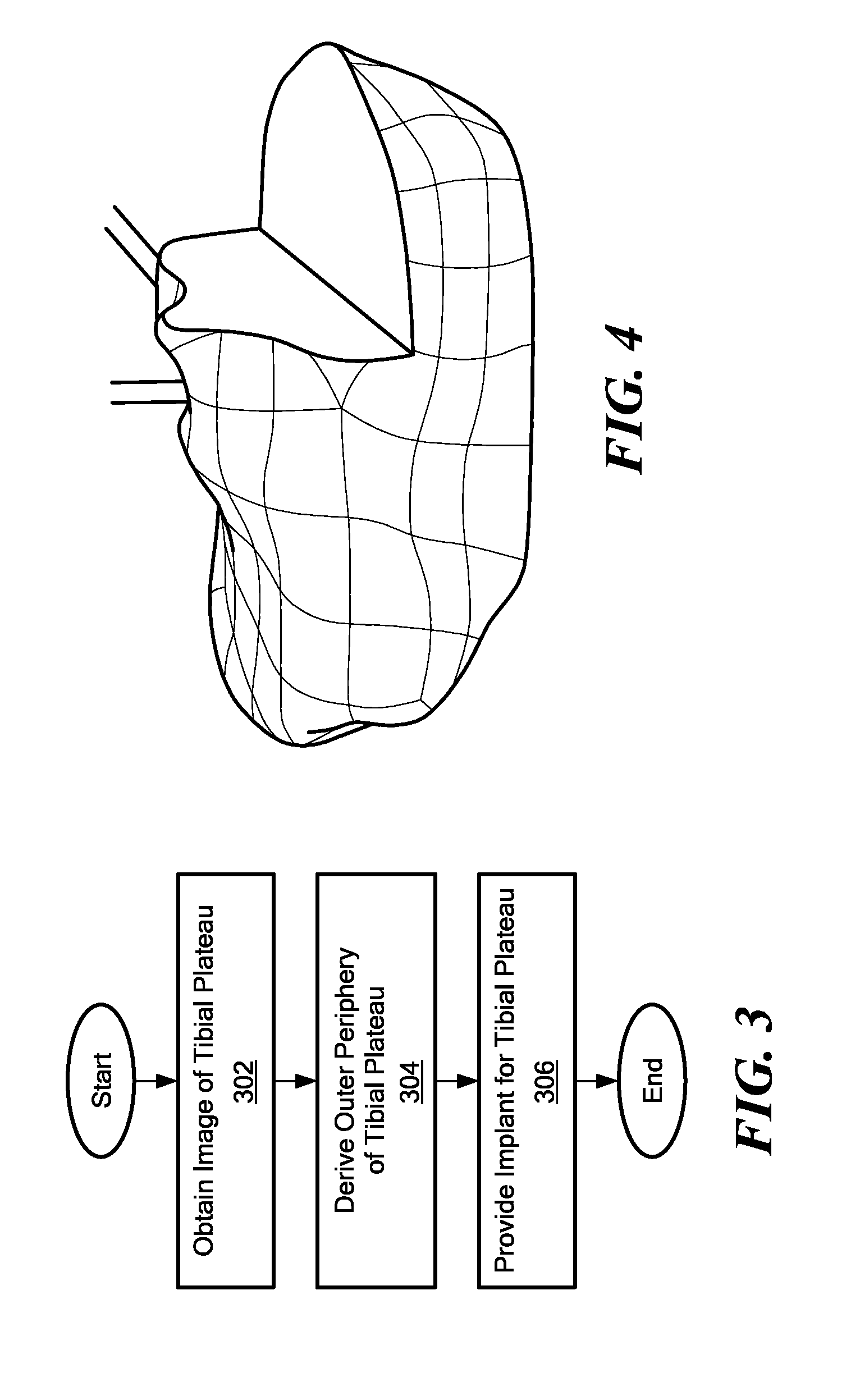
[0031]Various methods, systems and devices for joint arthroplasty are described to provide an implant for a tibial plateau that has an outer edge that substantially matches or corresponds to the outer periphery of the tibial plateau, either the entire periphery or at least a portion of the periphery. Preferably, the outer edge of the implant rests entirely on cortical bone to provide support for the implant. However, in some embodiments, only a portion of the outer edge of the device will rest on cortical bone.

[0032]Referring to FIG. 1, a resected portion of an upper (proximal) end of a tibia 10 is illustrated. The medial tibial plateau of the left tibia 10 is resected, and a lateral compartment of the tibia 10, including a meniscus 13, is left intact. In alternate embodiments, the lateral portion of the tibia 10 may be resected, instead, or both lateral and medial portions of the tibia 10 may be resected. Furthermore, the implant is not limited to the tibia, and may be applied to o...


PUM


Abstract

A method of joint arthroplasty includes obtaining an image of at least a portion of the tibial plateau. An outer periphery of at least a portion of the tibial plateau is derived based, at least in part, on the image. An implant is provided for the tibial plateau, the implant having a periphery that includes an outer edge that substantially matches the derived outer periphery of the tibial plateau.

Description

CROSS-REFERENCE TO RELATED APPLICATIONS[0001]This application claims priority to U.S. Provisional Application No. 61 / 034,014, filed Mar. 5, 2008, which is incorporated herein by reference.[0002]This application is related to U.S. application Ser. No. 10 / 997,407, filed Nov. 24, 2004, which is incorporated herein by reference.TECHNICAL FIELD[0003]The embodiments described herein relate to orthopedic systems, methods and devices. More particularly, systems, methods and devices for knee, hip, ankle, foot, shoulder, elbow, wrist and hand arthroplasty are provided.BACKGROUND ART[0004]It is common to resect the upper tibia during, for example, unicompartmental knee arthroplasty (and also bicompartmental and total knee arthroplasty), and insert a tibial implant. Typically, the tibial implant is selected from a limited, fixed number of sizes such that overhang of the implant over the resected tibial plateau is prevented. Towards this end, the tibial implant is often selected such that the im...

Claims


Application Information

Patent Timeline
IPC IPC(8): A61F2/38
CPCA61F2/30942A61F2/34A61F2/389A61F2310/00179A61F2002/30948A61F2002/3895A61F2/4081A61B2034/105A61B2034/108G06T19/00A61F2/38A61F2/3868
Inventor LANG, PHILIPPSTEINES, DANIELFITZ, WOLFGANG
Owner CONFORMIS
Why Eureka
Try Eureka