System and Method for Providing a One-Step Testing Architecture

a testing architecture and one-step technology, applied in the field of testing, can solve the problems of increasing the test time, affecting the test efficiency of the unit under test, and the drawbacks of current testing protocols, so as to eliminate or reduce the disadvantages and problems

Inactive Publication Date: 2009-09-10
FUJITSU LTD
View PDF20 Cites 6 Cited by
  • Summary
  • Abstract
  • Description
  • Claims
  • Application Information

AI Technical Summary

Benefits of technology

[0005]The present invention provides a method and a system for providing a one-step testing approach that substant...

Problems solved by technology

However, current testing protocols do have their drawbacks.
Typical problems in this area include increased test time, which is typically due to handling products when performing JTAG/programming and/or system tests of printed circuit boards (PCB) used in “hot insertion” systems.
Performing the JTAG/programming in the system creates three clear problems.
The first problem is the failure of a unit under test (UUT), which is done by the management complex unit (MCU) due to inserting the u...

Method used


Image

  • System and Method for Providing a One-Step Testing Architecture
  • System and Method for Providing a One-Step Testing Architecture

Examples


Embodiment Construction

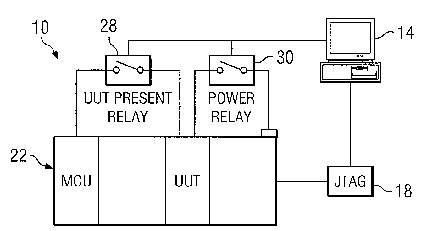
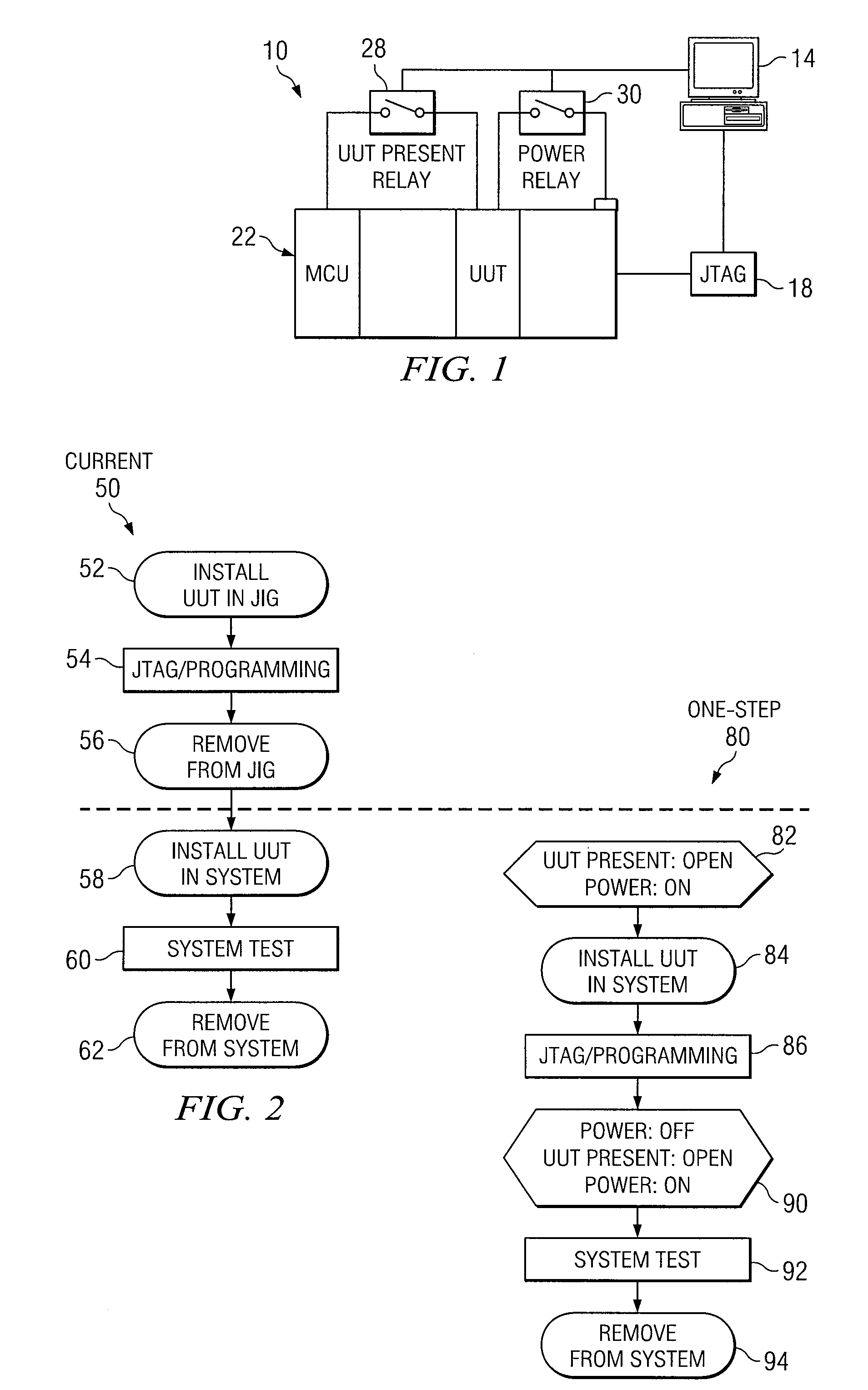
[0014]FIG. 1 is a simplified block diagram illustrating an example system 10 that provides a one-step testing protocol. System 10 includes a central processing unit (CPU) 14 and a Joint Test Action Group (JTAG) element 18, which can be connected as shown in FIG. 1 or connected through the backplane. System 10 also includes a shelf 22 that comprises a unit-under-test (UUT) component and a management complex unit (MCU), which ‘sees’ when a given board is installed. This particular connection needs to be broken such that the MCU does not see the board when it is initially plugged in, as detailed further below and with explicit reference to FIG. 2.

[0015]The spaces between the MCU and the UUT are simply slots of the shelf (which may or may not be empty). System 10 further includes a UUT present relay 28 (coupled to the MCU and the UUT) and a power relay 30 (coupled to the UUT). The backplane can be modified to isolate those two signals, where a relay is properly positioned for each compo...


PUM


Abstract

In one embodiment, a method includes powering on a testing system, whereby a unit present signal is included in the system, the unit present signal communicating to a management complex unit (MCU) that a unit under test (UUT) has been inserted into a corresponding architecture, the signal being sent through a relay such that it can be sent or connected at a later time. The UUT is installed in the system and a programming protocol is initiated. The system is then powered off, whereby the unit present signal is set to open and the system is subsequently powered on.
When the UUT is plugged in, the MCU does not see it. The system can include a second relay that allows power being fed to the UUT to be broken such that when the UUT is subsequently powered up, the board is reset and not removed from the architecture.

Description

TECHNICAL FIELD OF THE INVENTION[0001]This invention relates generally to the field of testing and, more specifically, to a system and a method for providing a one-step testing architecture.BACKGROUND OF THE INVENTION[0002]Joint Test Action Group (JTAG) testing is ubiquitous in today's circuit board manufacturing environment. However, current testing protocols do have their drawbacks. Typical problems in this area include increased test time, which is typically due to handling products when performing JTAG / programming and / or system tests of printed circuit boards (PCB) used in “hot insertion” systems.[0003]Performing the JTAG / programming in the system creates three clear problems. The first problem is the failure of a unit under test (UUT), which is done by the management complex unit (MCU) due to inserting the un-programmed PCB in the system. The second problem is the interference by the management complex trying to access the UUT while performing JTAG testing. The third problem is...

Claims


Application Information

Patent Timeline
IPC IPC(8): G06F1/26
CPCG06F1/263
Inventor CRAFTON, GREGORY L.
Owner FUJITSU LTD
Why Eureka
Try Eureka