
Physical quantity sensor

a sensor and physical technology, applied in the field of physical quantity sensors, can solve the problems of deterioration of air tight characteristics, large number of structural members, complex structure of sensors, etc., and achieve the effect of convenient retrieval

Inactive Publication Date: 2009-09-17
DENSO CORP
View PDF52 Cites 20 Cited by
  • Summary
  • Abstract
  • Description
  • Claims
  • Application Information

AI Technical Summary

Benefits of technology

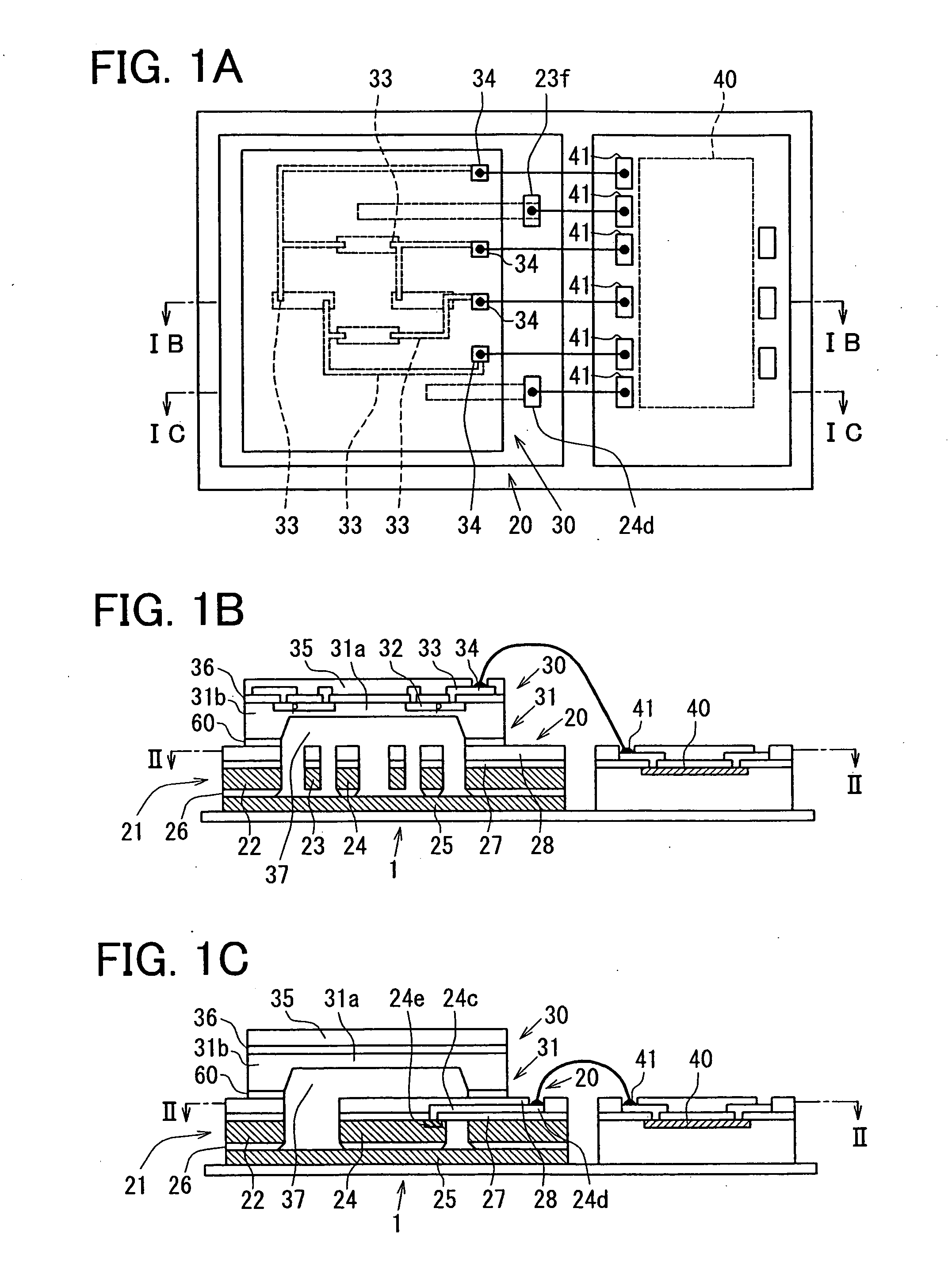
[0013]Alternatively, the first substrate may further include a support layer, an insulation layer, a conductive layer and a lower wiring. The support layer, the insulation layer and the conductive layer are stacked in this order. The first physical quantity detection element is disposed in the conductive layer. The lower wiring is sandwiched between the insulation layer and the conductive layer. The first physical quantity detection element is coupled with the second substrate through the lower wiring. This lower wiring provides strong construction, compared with a wire bonding sensor.
[0016]Alternatively, the processing circuit on the second substrate is opposite to the first substrate. In this case, the output signal from the processing circuit is easily retrieved. For example, a part of the protection film for covering an output wiring from the processing circuit is removed so that the output wiring is exposed from the protection film. Thus, the output signal from the processing circuit is easily retrieved.

Problems solved by technology

The technical idea disclosed in JP-A-2002-286571 has the following problems: That is, not only the structure of the sensor is made complex, but also the large number of structural members are required.
Furthermore, since there are many joined portions, the air tight characteristic may be deteriorated.
As a result, the technical idea disclosed in JP-A-2002-286571 has another problem that a large number of sensors having high precision can be hardly manufactured.
That is, since the pressure sensor and the acceleration sensor are arrayed side by side to be integrated within the same die, the area occupied by these sensors becomes bulky.
Furthermore, as explained in JP-A-6-347475, in the case where the sensor portion and the signal processing circuit are arranged on the same plane, there is another problem that the sensor area defined by combining the sensor unit with the signal processing circuit becomes bulky.

Method used


Image

  • Physical quantity sensor
  • Physical quantity sensor
  • Physical quantity sensor

Examples


second embodiment

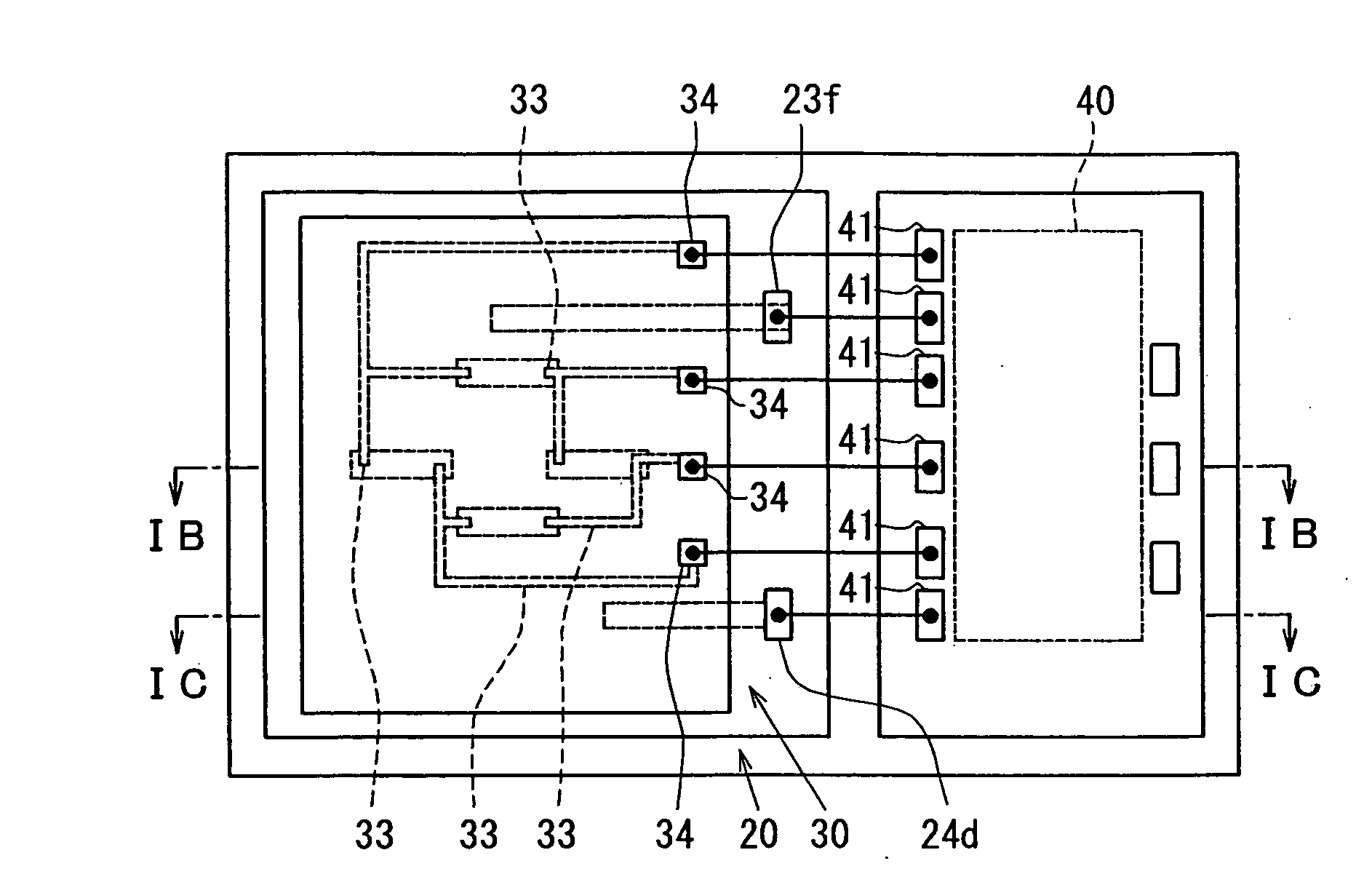
[0097]Referring now to FIG. 9A to FIG. 9C, a description is made of a composite type dynamic amount sensor 1 according to a second embodiment. This embodiment is different from the above-described first embodiment as to the following technical point: That is, a piezoelectric type pressure sensor 30 is adhered to a capacitance type acceleration sensor 20 by employing solder 91 and 92, and an air tight characteristic of a reference pressure chamber 37 is secured by an air tight annular ring 93. It should also be noted that the same reference numerals shown in the first embodiment will be employed as those for denoting the same, or similar structures indicated in the second embodiment, and explanations in this embodiment are omitted.

[0098]FIG. 9A is a sectional view for indicating the composite type dynamic amount sensor 1 according to the second embodiment, namely such a sectional view, taken along a line IXA-IXA of FIG. 9B and FIG. 9C. Also, FIG. 9B corresponds to FIG. 1B in the firs...

third embodiment

[0108]Referring now to FIG. 10A to FIG. 10C, a description is made of a composite type dynamic amount sensor 1 according to a third embodiment. This embodiment is different from the above-described second embodiment as to the following technical point: That is, the air tight characteristic of the reference pressure chamber 37 is secured by employing an NCF (Non-Conductive Film) 101. It should also be noted that the same reference numerals shown in the first embodiment, or the second embodiment will be employed as those for denoting the same, or similar structures indicated in the third embodiment, and explanations in this embodiment are omitted.

[0109]FIG. 10A is a sectional view for indicating the composite type dynamic amount sensor 1 according to the third embodiment, namely such a sectional view, taken along a line XA-XA of FIG. 10B and FIG. 10C. Also, FIG. 10B corresponds to FIG. 1B in the first embodiment, and FIG. 10C corresponds to FIG. 1C in the first embodiment.

[0110]As sho...

fourth embodiment

[0117]Referring now to FIG. 11, a description is made of a composite type dynamic amount sensor 1 according to a fourth embodiment. The fourth embodiment has the below-mentioned technical different points from those of the first embodiment. That is, in this embodiment, while a penetration electrode 111 is provided on a diaphragm 31, a signal of a capacitance type acceleration sensor 20 can be derived from the diaphragm 31 through the penetration electrode 111. It should be understood that the same reference numerals shown in the above-described respective embodiments will be employed as those for denoting the same, or similar structural elements in the fourth embodiment, and descriptions thereof are omitted.

[0118]FIG. 11 is a sectional view for showing the composite type dynamic amount sensor 1 according to the fourth embodiment, and corresponds to FIG. 1C in the first embodiment.

[0119]As indicated in FIG. 11, the penetration electrode 111 and an insulating film 112 have been formed...


PUM


Abstract

A physical quantity sensor for detecting a physical quantity includes: a first substrate having a first physical quantity detection element; a second substrate having a second physical quantity detection element, wherein the second substrate contacts the first substrate; and an accommodation space disposed between the first substrate and the second substrate. The first physical quantity detection element is disposed in the accommodation space. The first physical quantity detection element is protected with the first substrate and the second substrate since the first physical quantity detection element is sealed in the accommodation space.

Description

CROSS REFERENCE TO RELATED APPLICATIONS[0001]This application is a continuation of U.S. application Ser. No. 11 / 808,774, which was filed on Jun. 12, 2007 and is based on Japanese Patent Applications No. 2006-163877 filed on Jun. 13, 2006, and No. 2007-60596 filed on Mar. 9, 2007, the disclosures of which are incorporated herein by reference.FIELD OF THE INVENTION[0002]The present invention relates to a physical quantity sensor.BACKGROUND OF THE INVENTION[0003]As technical ideas capable of combining pressure sensors with other dynamic amount (i.e., physical quantity) detecting sensors in module forms, one technical idea is disclosed in JP-A-2002-286571, and another technical idea is described in Japanese magazine “DEMPA-SHINBUN HIGH TECHNOLOGY” issued by DEMPA-SHINBUN newspaper publisher on May 13, 2004.[0004]The technical idea disclosed in JP-A-2002-286571 is related to the pressure speed sensor equipped with the pressure detecting function for detecting the air pressure of the tire...

Claims


Application Information

Patent Timeline
Patent Type & Authority Applications(United States)
IPC IPC(8): G01R27/26
CPCB81B7/02B81B2201/0235H01L2924/1461H01L2224/49175H01L2224/48137B81B2201/0264B81B2207/07B81C2203/0118G01L9/0042G01P1/023G01P15/0802G01P15/125H01L2224/48091H01L2924/00014H01L2924/00H01L2224/05553H01L2224/05554
Inventor FUJII, TETSUOKAWASAKI, EISHI
Owner DENSO CORP
Learn More