Tool for removal of center cover of a wheel rim

a technology for center covers and tools, which is applied in the direction of lifting devices, crowbars, etc., can solve problems such as scraping of wheel covers, and achieve the effect of facilitating tool manipulation

Inactive Publication Date: 2009-09-17
LISLE CORPORATION
View PDF4 Cites 17 Cited by
  • Summary
  • Abstract
  • Description
  • Claims
  • Application Information

AI Technical Summary

Benefits of technology

[0005]Briefly, the present invention comprises a tool for removal of the center cover of a wheel rim. The tool is comprised of a unitary, elongate, generally cylindrical rod having a first hook end and an opposite hook end with a straight connecting cylindrical rod section joining the hook ends. The hook ends are each fashioned with a similar configuration, but have a different size and different orientation. Thus, each hook end is comprised of a series of first and second oppositely radiused bends which terminate with a flat-sided blade extension with an end prong. An important feature of the tool is the universality of the tool inasmuch as the opposite hook ends are appropriately sized and dimensioned and configured to enable utilization of the tool with almost any wheel cover or hub center cover. Additionally, the hook ends and the center connecting section all lie in the same plane though the blades and the end of the hook ends extend in opposite directions. This facilitates manipulation of the tool.
[0008]Another object of the invention is to provide a center cap which is designed to minimize the possibility of scratching or marring either the rim or the center cap associated with a rim of a motor vehicle wheel.
[0009]Another object of the invention is to provide a tool for removal of the center cap or hub cap from a wheel of a motor vehicle which is easy to use, inexpensive, rugged, and highly utilitarian.

Problems solved by technology

The utilization of a screwdriver or similar tool may result in scratching of the wheel cover.

Method used


Image

  • Tool for removal of center cover of a wheel rim
  • Tool for removal of center cover of a wheel rim
  • Tool for removal of center cover of a wheel rim

Examples


Embodiment Construction

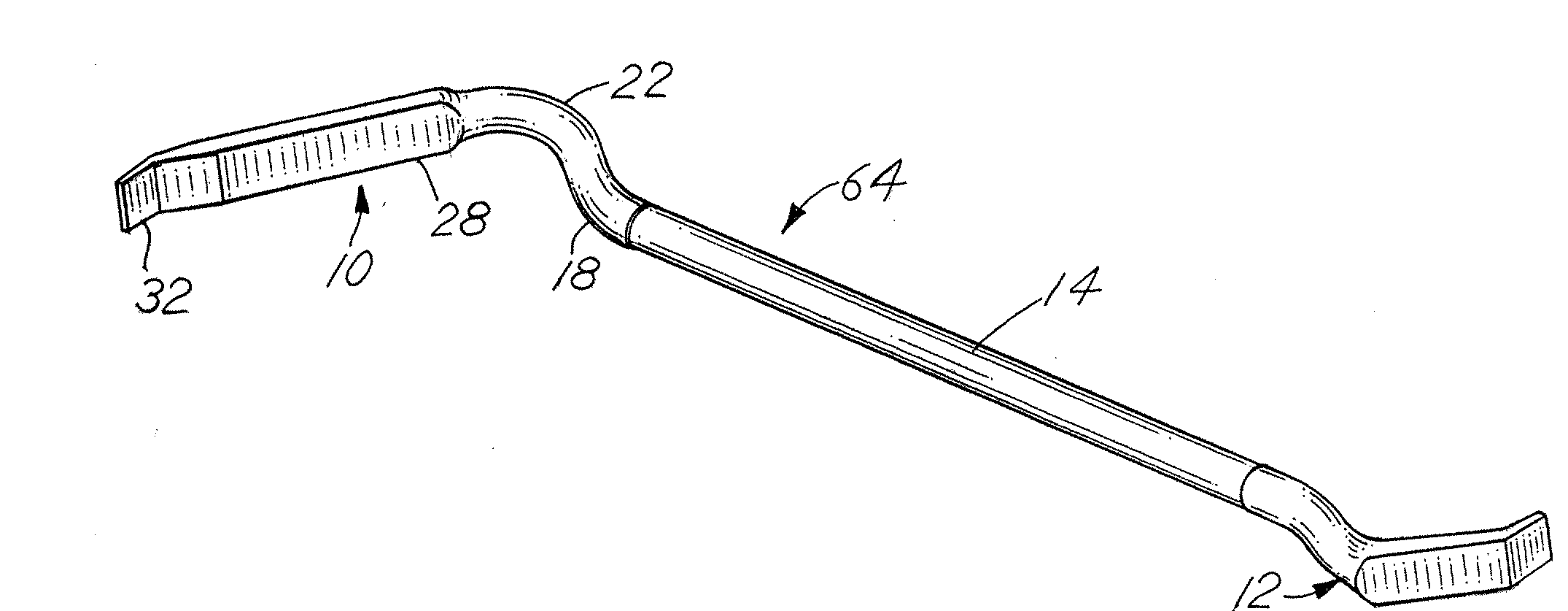
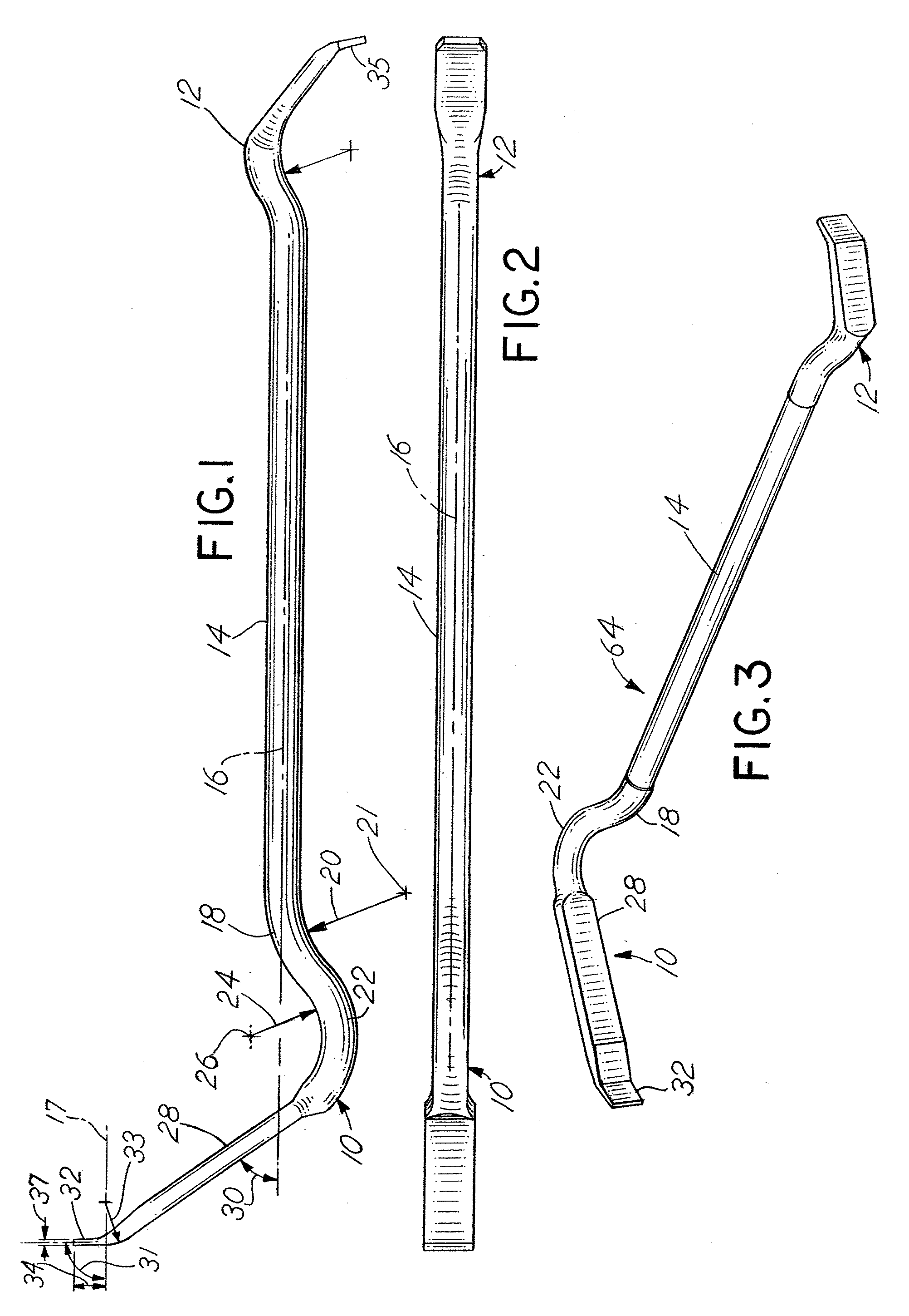
[0018]Referring to the figures, the tool of the invention is comprised of a unitary, elongate, generally cylindrical rod. The cylindrical rod includes a first hook end 10, an opposite or second hook end 12, and a connecting section 14 joining the first end 10 and the second end 12. The first end 10 and the second end 12 all lie in a plane or are coplanar with the connecting rod section 14 so that the tool may lay flat on a flat, planar surface when viewed as depicted, for example, in FIG. 2. The connecting section 14 is a cylindrical rod having a diameter in the range of 0.25 to 0.5 inches. The length of the connecting section 14 is in the range of 6-8 inches. Connecting section 14 includes a straight, center line axis 16. The opposite first and second ends 10, 12 each follow generally arcuate pathways and are integrally joined to the center connecting section 14.

[0019]Thus, the connecting section 14 defines a straight, longitudinal axis 16. The first hook end 10 and second hook end...


PUM


Abstract

A tool for removal of a center cover of a wheel rim includes a first and second opposite hook ends connected by a cylindrical rod center section. Each of the hook ends is differently sized, although the ends are generally mirror image configurations of one another and each includes first and second curved sections joined to an extended flat, planar section with an end prong.

Description

BACKGROUND OF THE INVENTION[0001]In a principal aspect the present invention relates to a tool which is designed to facilitate the removal of a center cover of a wheel rim of a motor vehicle, or alternatively, the hub cap cover at the center of a wheel rim.[0002]Many modern motor vehicles include a wheel rim wherein the spokes of the wheels are visible, but the center of the wheel rim, which is attached by lug nuts to a wheel axle, are not exposed, but are, in fact, covered by a center cover. This center cover or hub cover or cap is typically retained on the wheel rim by a detent mechanism which enables snapping of the hub cover onto the wheel rim. Multiple designs of such hub covers, or center covers, are or have been adopted for motor vehicles.[0003]When servicing a vehicle, it is often necessary to remove the wheel, for example, to replace the tire or to have access to the outer end of the axle. As a first step in such servicing, it is typically necessary to remove the hub cover ...

Claims


Application Information

Patent Timeline
Patent Type & Authority Applications(United States)
IPC IPC(8): B66F15/00
CPCB66F15/00
Inventor KURTZ, SCOTTY R.
Owner LISLE CORPORATION
Why Eureka
Try Eureka