Image pick-up apparatus, image pick-up method and recording medium

a technology of image pick-up and image, which is applied in the direction of exposure control, optical radiation measurement, instruments, etc., can solve the problem of not being able to obtain a suitable imag

Inactive Publication Date: 2009-09-17
FUJIFILM CORP
View PDF4 Cites 78 Cited by
  • Summary
  • Abstract
  • Description
  • Claims
  • Application Information

AI Technical Summary

Benefits of technology

[0006]However, the shooting procedure with the slow synchronized flash effect has a problem that a suitable image can not be obtained without an optimum light amount by flash and an optimum light amount by

Problems solved by technology

However, the shooting procedure with the slow synchronized flash effect has a problem that a suitable image can not be obtained without an optimum light amount by flash and an optimum light amount by lon

Method used


Image

  • Image pick-up apparatus, image pick-up method and recording medium
  • Image pick-up apparatus, image pick-up method and recording medium
  • Image pick-up apparatus, image pick-up method and recording medium

Examples


first embodiment

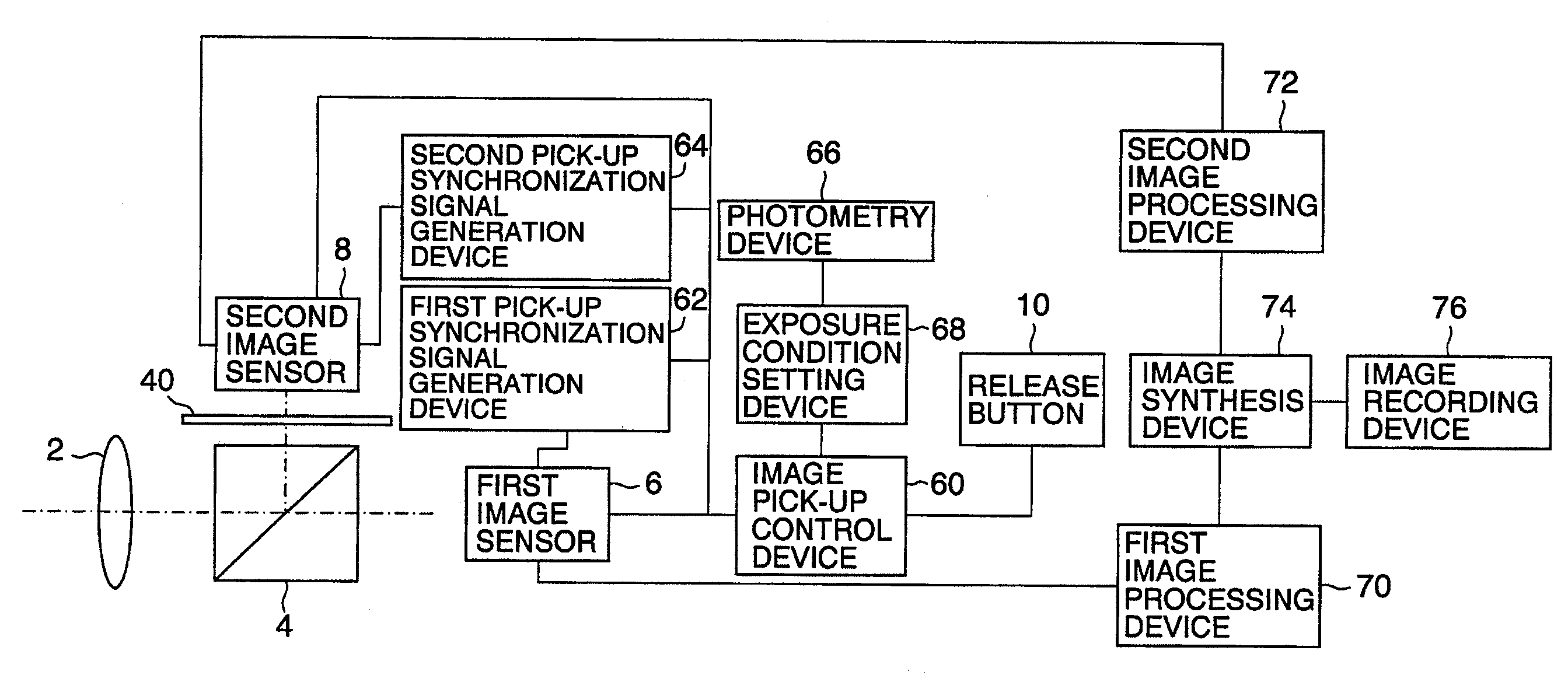
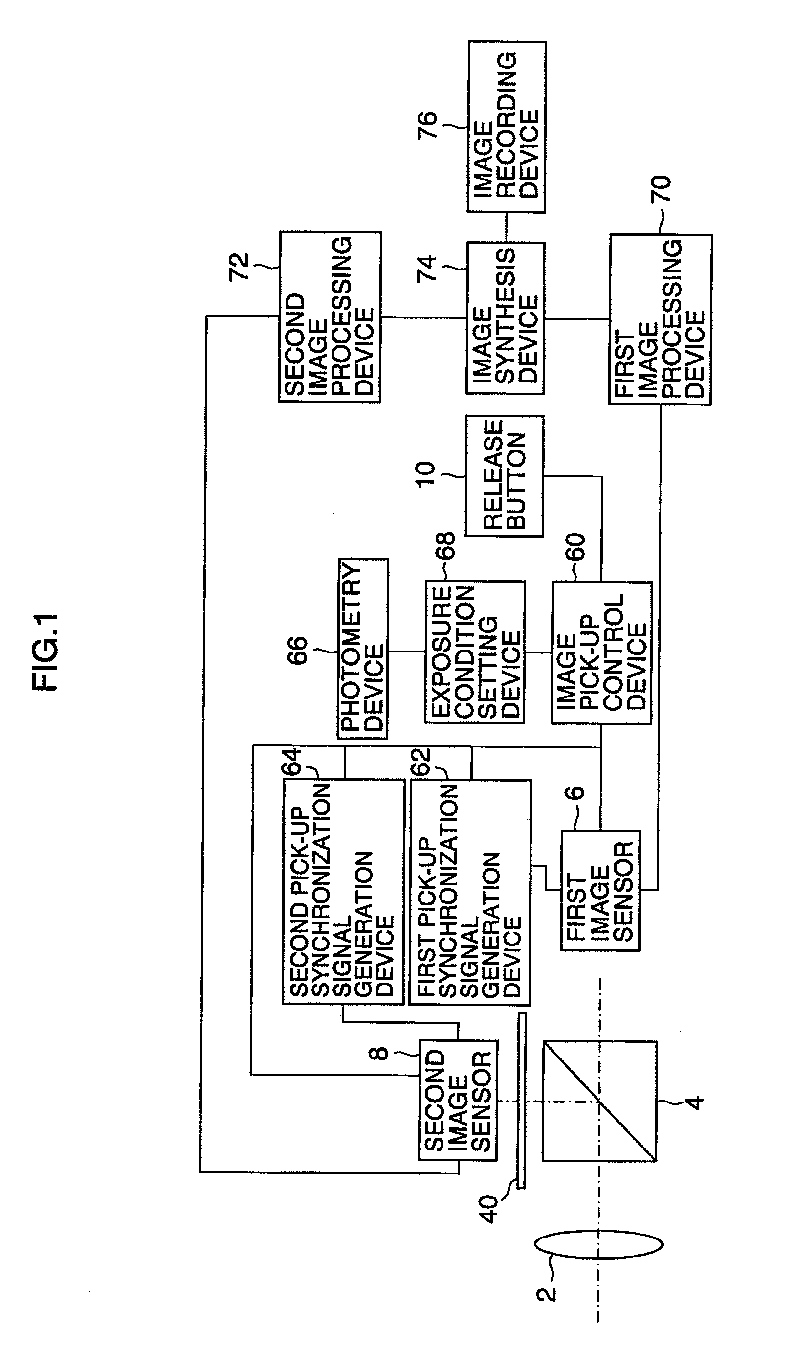
[0065]FIG. 1 is a block diagram illustrating the image pick-up apparatus according to the present invention. The image pick-up apparatus includes a lens 2 on a light path of an image light, a beam splitter 4 that is a light dispersing device, and a first image sensor 6, and further includes second image sensor 8 located at a position where the incident light is forwarded after being dispersed by the beam splitter 4.

[0066]Pulses for cleaning unnecessary charges stored in the first image sensor 6 and the second image sensor 8 and shutter gate pulses synchronized to an pick-up synchronization signal for reading out the accumulated charges can be, independently and respectively, added to the first image sensor 6 and the second image sensor 8 from a first pick-up synchronization signal generation device 62 and a second pick-up synchronization signal generation device 64 controlled by an image pick-up control device 60. The time period from the pulse for cleaning the unnecessary charges t...

second embodiment

[0106]In the second embodiment as illustrated in FIG. 11, the ND filter 40 that is the light amount adjustment device is not provided between the beam splitter 4′ and the second image sensor 8. The beam splitter 4′ having a ratio of the amount of transmitting light and the amount of reflecting light of, for example, 8:1 is used.

[0107]Accordingly, even if the first shutter of the first image sensor 6 is set to eight times (exposure time is set to ⅛) the second shutter speed of the second image sensor 8, the same amount of exposure light can be obtained.

[0108]FIG. 12 illustrates a first example of a table for setting the exposure conditions of the first image sensor 6 and the second image sensor 8 based on photometered brightness of an object. The table illustrates relationships between the brightness of the object, and shutter speeds and apertures. As illustrated in the first embodiment in FIG. 1, the table illustrated here is applied for a case where the ND filter 40 is inserted bet...

third embodiment

[0112]FIG. 14 is a block diagram illustrating the image pick-up apparatus according to the present invention. The same numeral references are given to the parts in common with the block diagram in the first embodiment as illustrated in FIG. 1, and the details of the description will be omitted.

[0113]The difference between FIG. 14 and FIG. 1 is that FIG. 14 includes a first sensitivity adjustment device 78 and a second sensitivity adjustment device 80 for adjusting the ISO sensitivity of the first and second image signals output from the first image sensor 6 and the second image sensor 8. Further, the ND filter 40 can be inserted or retracted between the beam splitter 4 and the second image sensor 8.

[0114]FIG. 15 illustrates the second example of the table for setting the first and second exposure condition based on the photometered brightness of the object. The table illustrates relationships of the brightness of the object and the shutter speed, the aperture, and the ISO sensitivit...


PUM


Abstract

Image light from an object is dispersed by a light dispersing device. When a plurality of image sensors are used for picking up images, an image in which a moving object is stopped is picked up with a high shutter speed, and at the same time, a motion-blurred image in which the moving object is picked up at a slow shutter speed. The obtained images are synthesized. The synthesized image has a slow synchronized flash effect. Accordingly, an image having a slow synchronized flash effect can be obtained without using a flash.

Description

BACKGROUND OF THE INVENTION[0001]1. Field of the Invention[0002]The present invention relates to an image pick-up apparatus and an image pick-up method that enable to obtain a slow synchronized image using a plurality of image sensors.[0003]2. Description of the Related Art[0004]In recent years, owing to camera shake compensation and improvement of auto focus of a digital camera, even a beginner causes a substantially lower risk of picking up a camera-shaken image or a blurred image. This is because from demands by general users, the camera makers have made efforts on improvement of the cameras. However, some people who have interests in photographing demand to actively generate motion blur to express movements of an object or to obtain an image in which a motion-blurred image and an motionless image (non-motion-blurred image) appearing that the movement stops for a moment during the movement, co-exist. A shooting procedure of “slow synchronized flash” is a method to pick up such an...

Claims


Application Information

Patent Timeline
IPC IPC(8): H04N5/235G03B7/091G03B7/28G03B17/00G03B19/06H04N5/225H04N5/335H04N5/353H04N5/355
CPCH04N5/23248H04N5/23293H04N5/2351H04N5/772H04N5/2355H04N5/35554H04N5/2353H04N23/68H04N23/631H04N23/741H04N23/71H04N23/73H04N25/583
Inventor SENBA, TAKEHIKO
Owner FUJIFILM CORP
Why Eureka
Try Eureka