Turbidity sensor and electric home appliance having the same

a technology of turbidity sensor and electric home appliance, which is applied in the direction of cleaning equipment, other washing machines, instruments, etc., can solve the problems of scale, contamination of the surface of the turbidity sensor b>3/b>, and the error in the measurement of so as to increase the light amount and increase the turbidity of the water

Inactive Publication Date: 2009-09-17
SAMSUNG ELECTRONICS CO LTD
View PDF0 Cites 21 Cited by
  • Summary
  • Abstract
  • Description
  • Claims
  • Application Information

AI Technical Summary

Benefits of technology

[0020]The more the ratio of the amounts of the light may be incr...

Problems solved by technology

However, when the above conventional turbidity sensor 3 is used in a container 1 filled with water for a long time, the surface of the turbidity sensor 3 is covered with contaminants, such as scale.
Consequen...

Method used


Image

  • Turbidity sensor and electric home appliance having the same
  • Turbidity sensor and electric home appliance having the same
  • Turbidity sensor and electric home appliance having the same

Examples


first embodiment

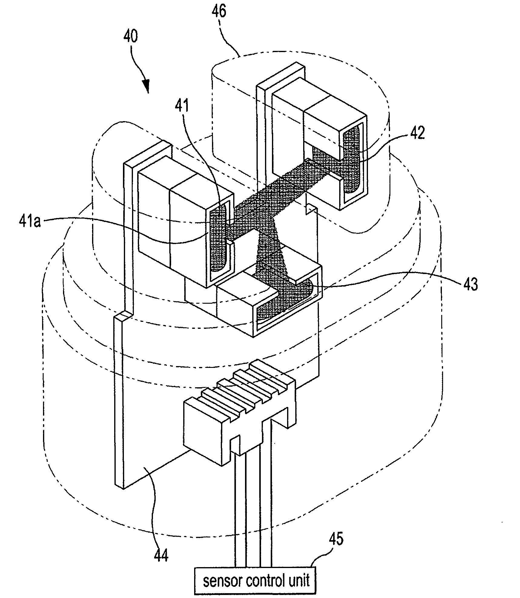
[0050]FIG. 3 is a view illustrating the structure of a turbidity sensor in accordance with a

[0051]In FIG. 3, a turbidity sensor 40 includes one light emitting part 41, which is installed on a substrate 44 and emits light, and first and second light receiving parts 42 and 43 respectively receiving the light emitted from the light emitting part 41. Generally, a light emitting element, such as an LED, for example, is used as the light emitting part 41, and light receiving elements, such as photo transistors or photo diodes, for example, are used as the first and second light receiving parts 42 and 43.

[0052]The light emitting part 41 is configured such that light can travel straight in a narrow range and is disposed in a case 41a. The first light receiving part 42 is disposed opposite to the light emitting part 41 so as to be located in the straight traveling range of the light emitted from the light emitting part 41, and the second light receiving part 43 is disposed at a position at w...

second embodiment

[0068]FIG. 7 is a conceptual view of a turbidity sensor in accordance with a Some parts of FIG. 7, which are substantially the same as those of FIG. 4B, are denoted by the same reference numerals even though they are depicted in different drawings, and a detailed description thereof will thus be omitted because it is considered to be unnecessary.

[0069]A turbidity sensor 40 of FIG. 7 further includes a third light receiving part 47, in addition to the components of the turbidity sensor 40 of FIG. 4B. That is, the turbidity sensor 40 includes three light receiving parts 42, 43, and 47.

[0070]In FIG. 7, the third light receiving part 47 is disposed at a position opposite to the second light receiving part 43 to receive a portion of light emitted from the light emitting part 41, which is scattered by particles in water. In order to use a conventional cover 46 as it is, the third light receiving part 47 may be disposed substantially in parallel with the second receiving part 43 on the su...


PUM


Abstract

Disclosed are a turbidity sensor, which correctly senses a turbidity of water although the surface of the turbidity sensor is covered with foreign substances, such as scale, and an electric home appliance having the turbidity sensor. The turbidity sensor includes a light emitting part emitting light, a first light receiving part receiving light emitted from the light emitting part and travelling straight, a second light receiving part receiving light emitted from the light emitting part and scattered, and a control unit determining a turbidity of water according to a ratio of the amounts of the light received by the plurality of light receiving parts. The first light receiving part is installed in a direction of directly receiving the light emitted from the light emitting part, and the second light receiving part is installed in another direction of not directly receiving the light emitted from the light emitting part.

Description

CROSS-REFERENCE TO RELATED APPLICATIONS[0001]This application claims the benefit of Korean Patent Application No. 2008-0023856, filed Mar. 14, 2008, in the Korean Intellectual Property Office, the disclosure of which is incorporated herein by reference.BACKGROUND[0002]1. Field[0003]The present invention relates to a turbidity sensor and an electric home appliance having the same, and more particularly, to a turbidity sensor, which correctly senses the turbidity of water although the surface of the turbidity sensor is covered with foreign substances, such as scale, and an electric home appliance having the turbidity sensor.[0004]2. Description of the Related Art[0005]Some products among electric home appliances using water, such as washing machines, dishwashers, etc., have a turbidity sensor installed therein to measure the turbidity, i.e., pollution level of water, and change a washing operation according to the sensed turbidity. These electric home appliances change a washing frequ...

Claims


Application Information

Patent Timeline
IPC IPC(8): G01N21/51
CPCA47L15/0018A47L15/4297G01N21/532D06F39/004A47L2401/10D06F34/22D06F2103/20D06F2105/52D06F2105/62
Inventor HAN, JEONG SUPYO, SANG YEONCHOI, HYEN YOUNGKIM, SUNG HOONHAN, SEONG JOOJC, SU HOLEE, SANG JUNYU, SO JUNGRYU, O. DO
Owner SAMSUNG ELECTRONICS CO LTD
Why Eureka
Try Eureka