
Card fixing structure

Inactive Publication Date: 2009-09-17
INVENTEC CORP
View PDF12 Cites 1 Cited by
  • Summary
  • Abstract
  • Description
  • Claims
  • Application Information

AI Technical Summary

Benefits of technology

[0009]The conventional air deflector merely has an airflow guide effect and cannot provide any fixing functions. Therefore, when a card needs to be installed in a server, a large number of fixing members are used, which results in a higher manufacturing cost, and increases the difficulty in installation. Accordingly, the present invention is directed to a card fixing structure which is easy to be assembled or disassembled and has a lower manufacturing cost.
[0011]According to the card fixing structure of the present invention, the air deflector catches the card to securely fix the card in the card holder, thereby reducing the number of fixing members such as screws for fixing the card. Further, the catch relationship enables an easier repair and expansion of the card. As described above, the catch relationship can simplify the use of fixing members, reduce the manufacturing cost, and also enables an easier assembly or disassembly of the card.

Problems solved by technology

The conventional air deflector merely has an airflow guide effect and cannot provide any fixing functions.
Therefore, when a card needs to be installed in a server, a large number of fixing members are used, which results in a higher manufacturing cost, and increases the difficulty in installation.

Method used


Image

  • Card fixing structure
  • Card fixing structure
  • Card fixing structure

Examples


Embodiment Construction

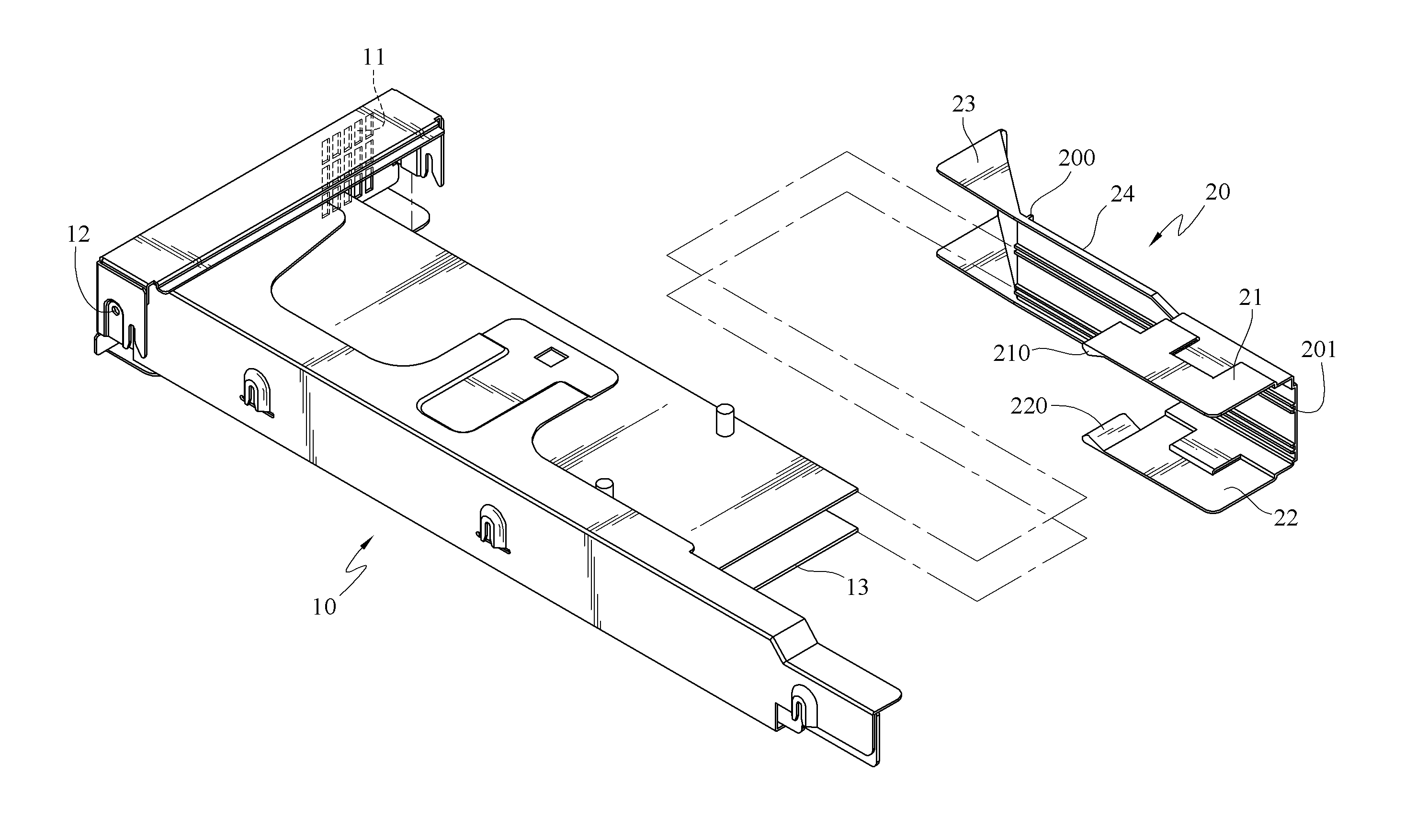
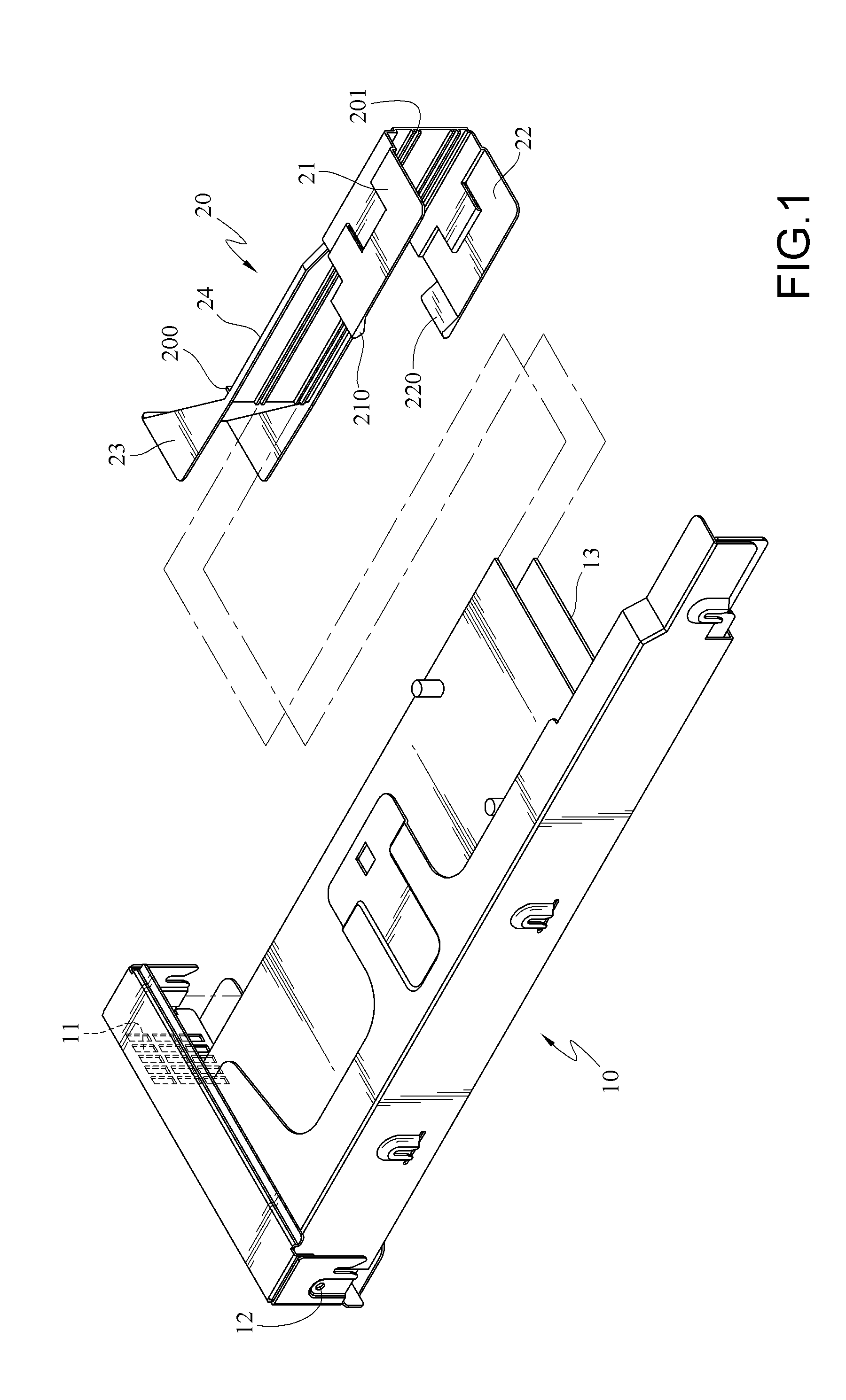
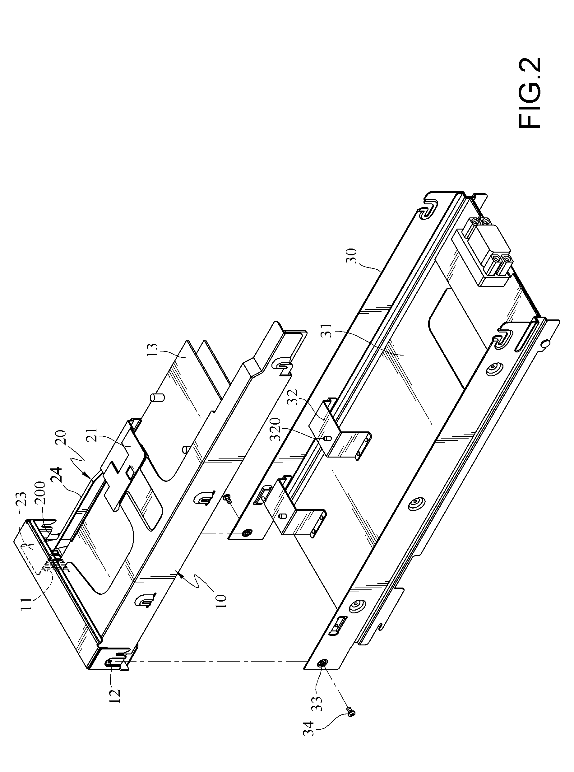
[0017]Referring to FIGS. 1 and 2 together, a card fixing structure of the present invention is shown. The card fixing structure includes a card holder 10, an air deflector 20, and a base 30.

[0018]The card holder 10 is used for disposing at least one card 13 and has an air outlet 11 at its one end, and a screw hole 12 respectively on its two sides and adjacent to the air outlet 11.

[0019]FIG. 3 is a perspective view of an appearance of an air deflector of the present invention. The air deflector 20 is clamped on one side of the card holder 10 and has a clamp portion 24. The clamp portion 24 has an upper clip 21 and a lower clip 22. The upper clip 21 has an upper protrusion 210 and the lower clip 22 has a lower protrusion 220. The upper protrusion 210 and the lower protrusion 220 respectively catch an upper edge and a lower edge of the card holder 10, so as to position the air deflector 20 at the card holder 10. The clamp portion 24 has at least one positioning rib 200 on its one side....


PUM


Abstract

A card fixing structure includes a card holder for disposing at least one card. The card holder has an air deflector clamped on its one side. The air deflector catches the card to securely fix the card in the card holder, thereby reducing the number of fixing members and the manufacturing cost. Also, the card, the air deflector, and the card holder are easy to be assembled or disassembled.

Description

CROSS-REFERENCE TO RELATED APPLICATIONS[0001]This non-provisional application claims priority under 35 U.S.C. § 119(a) on Patent Application No. 097204454 filed in Taiwan, R.O.C. on Mar. 14, 2008 the entire contents of which are hereby incorporated by reference.BACKGROUND OF THE INVENTION[0002]1. Field of Invention[0003]The present invention relates to a casing, in particular, to a card fixing structure which is easily to be assembled or disassembled and has a lower manufacturing cost.[0004]2. Related Art[0005]Servers are a kind of computers having quicker operation speed and superior functions. A server has a plurality of cards therein for providing operation, audio-visual, and other relevant electronic functions. The cards rely on the chips disposed thereon to offer corresponding performances. However, the chips when operating may generate greater heat, which will damage the chips. In order to prevent overheating of the chips, the temperature needs to be lowered properly.[0006]A c...

Claims


Application Information

Patent Timeline
IPC IPC(8): G06F1/20
CPCG06F1/185
Inventor LIN, YEN-CHENG
Owner INVENTEC CORP
Learn More