
Heat dissipation fan

a heat dissipation fan and fan body technology, applied in the direction of non-positive displacement fluid engines, piston pumps, pump components, etc., can solve the problems of increased friction between the shaft and the bearing, deterioration of the performance of the heat dissipation fan, and noise or malfunction of uncomfortable effects

Inactive Publication Date: 2009-09-17
FU ZHUN PRECISION IND SHENZHEN +1
View PDF18 Cites 10 Cited by
  • Summary
  • Abstract
  • Description
  • Claims
  • Application Information

AI Technical Summary

Benefits of technology

[0005]A typical heat dissipation fan comprises a fan housing having a central tube extending upwardly therefrom, a bearing received in the central tube, a stator mounted around the central tube, and a rotor rotatable with respect to the stator. The rotor includes a hub and a shaft extending from the hub into the bearing. The central tube has an opening defined at a top end thereof. The bearing is inserted into the central tube through the opening. Lubricating oil is injected into the central tube to lubricate the bearing and the shaft. A lubricating effect of the bearing and the shaft can be properly maintained when the heat dissipation fan is vertically mounted. However, when the heat dissipation fan is mounted in an upside-down manner, the lubricating oil will leak out of the central tube through the opening of the central tube and the amount of the lubricating oil in the bearing is thus gradually reduced. The friction between the shaft and the bearing is therefore increased due to a decrease of the lubricating oil, which results in uncomfortable noise or malfunction being generated. As a result, the performance of the heat dissipation fan deteriorates, and the life-span of the fan is accordingly shortened.

Problems solved by technology

The friction between the shaft and the bearing is therefore increased due to a decrease of the lubricating oil, which results in uncomfortable noise or malfunction being generated.
As a result, the performance of the heat dissipation fan deteriorates, and the life-span of the fan is accordingly shortened.

Method used


Image

  • Heat dissipation fan
  • Heat dissipation fan
  • Heat dissipation fan

Examples


Embodiment Construction

[0014]Reference will now be made to the drawings to describe the various present embodiments in detail.

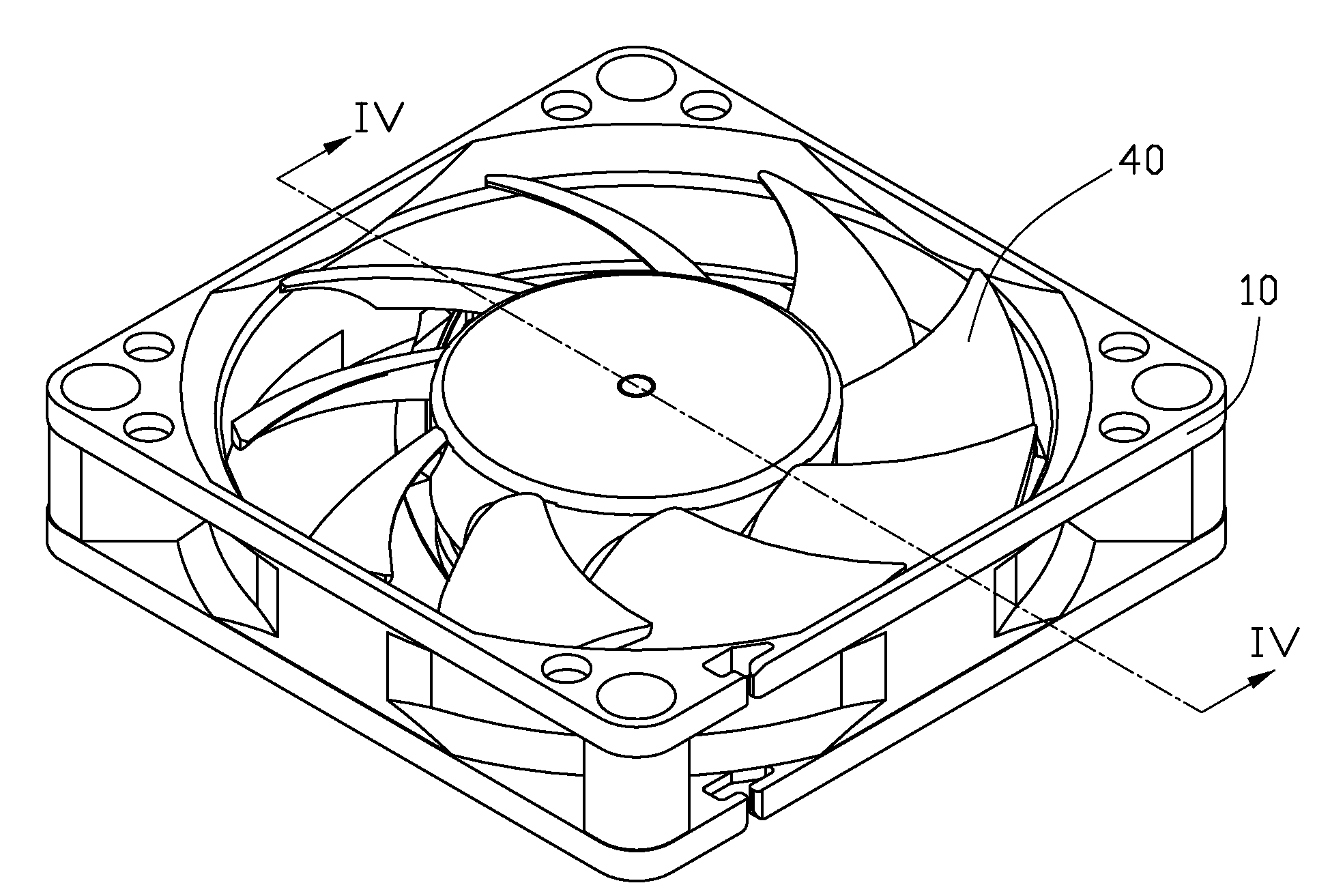
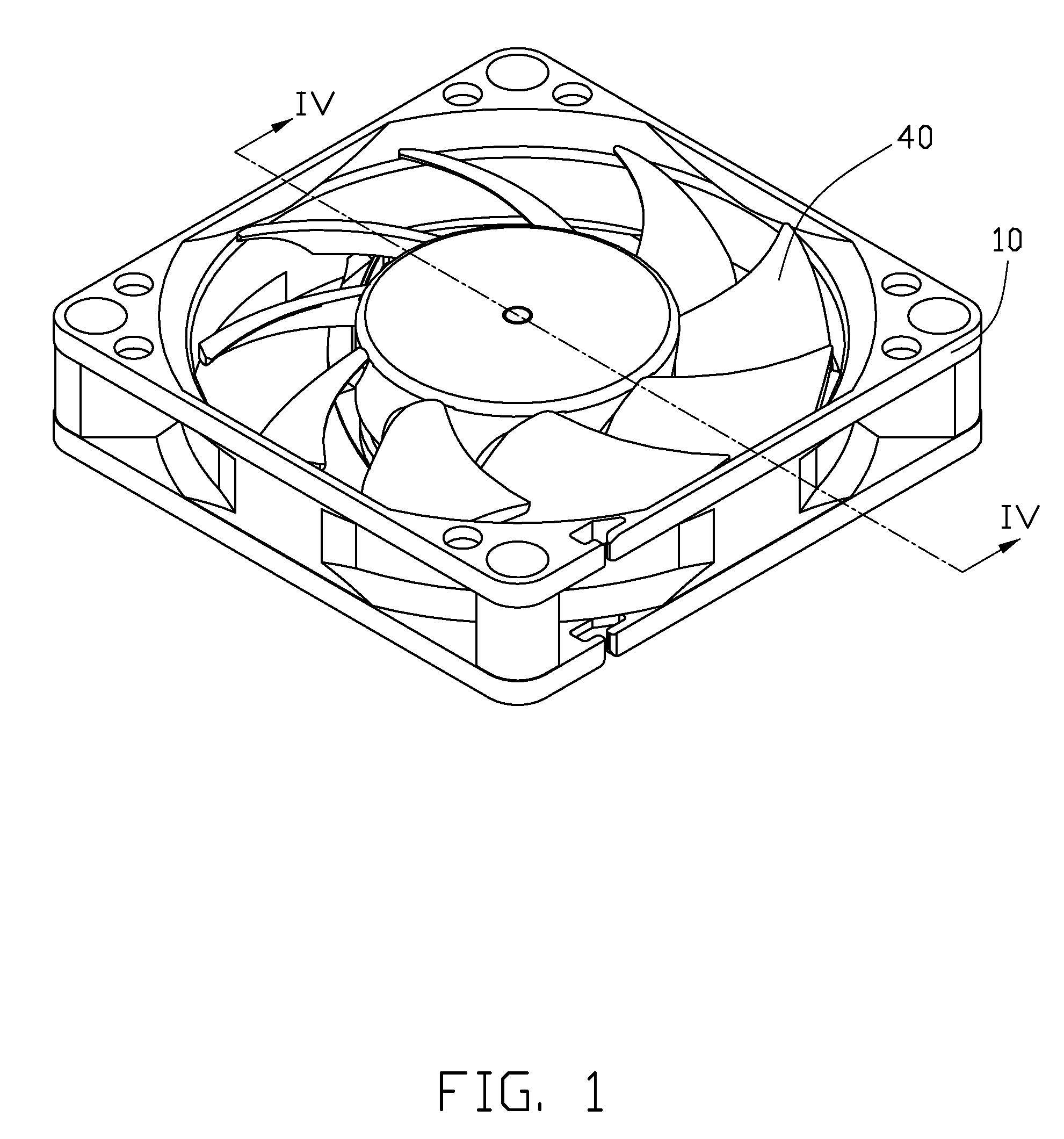
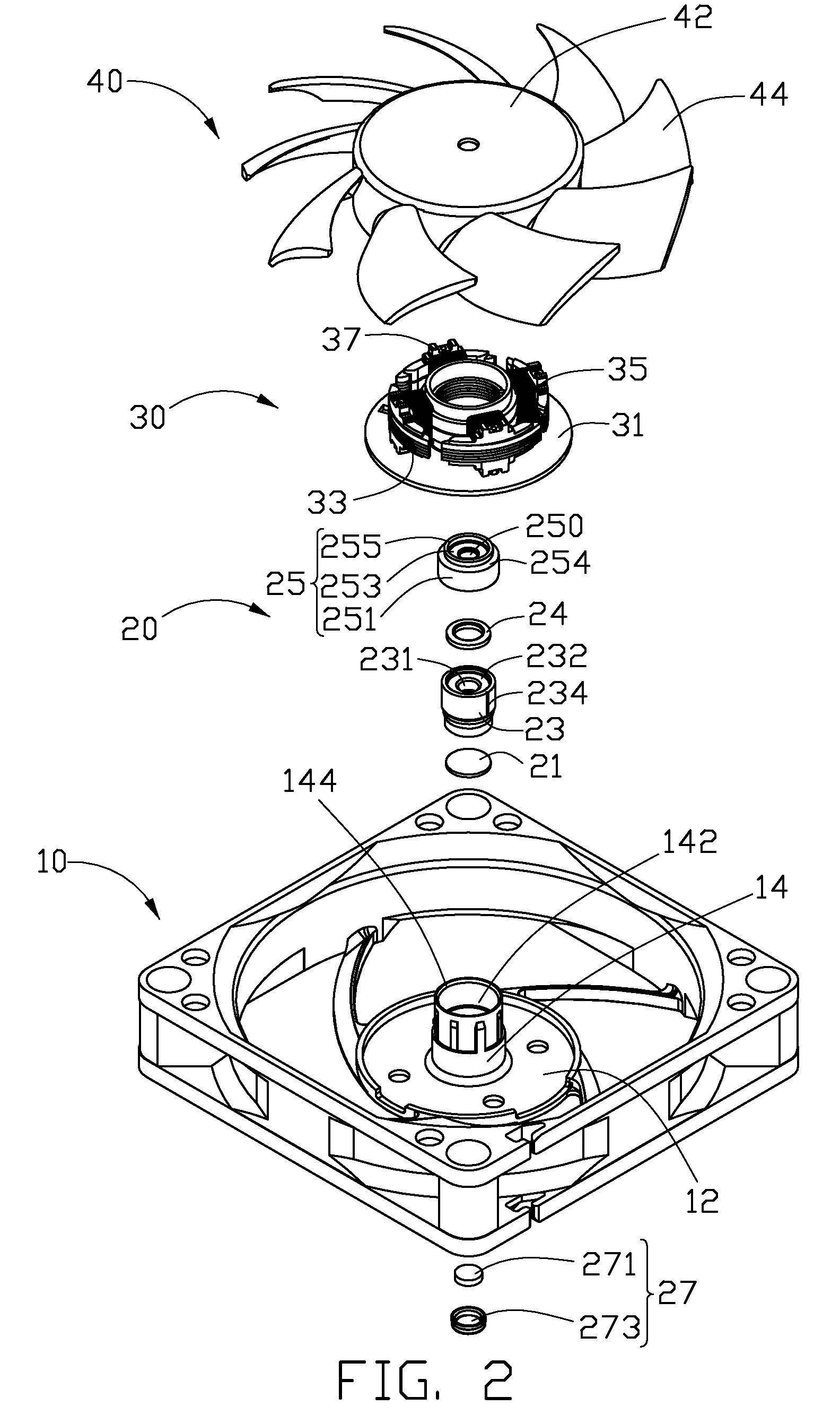
[0015]Referring to FIGS. 1-3, a heat dissipation fan according to an embodiment includes a rotor 40, a stator 30 in respect to which the rotor 40 is rotatable, a fan housing 10 receiving the rotor 40 and the stator 30 therein, and a bearing assembly 20.

[0016]The fan housing 10 comprises a base 12 and a central tube 14 extending upwardly from a top surface of a central portion of the base 12. The central tube 14 defines a central hole 142 therein and forms an open end at a top portion thereof. An annular recess 144 is formed on an inner circumference of the top portion of the central tube 14. The annular recess 144 communicates with the central hole 142. The top portion of the central tube 14 has an inner diameter which is larger than that of the other portion of the central tube 14. A receiving concave 120 is formed on a bottom surface of the central portion of the base 12. The rec...


PUM


Abstract

An exemplary heat dissipation fan includes a fan housing 10, a bearing assembly 20, a stator 30 and a rotor 40. The fan housing includes a base 12 and a central tube 14 extending upwardly from the base. The bearing assembly includes a bearing 23 received in the central tube, a porous wick element 24 and a locking washer 25. The stator is mounted around the central tube. The rotor includes a shaft 47 extending through a bearing hole 231 of the bearing. The locking washer is mounted around the shaft and fixed on a top end of the central tube. The locking washer, the bearing and the shaft cooperatively form an oil reservoir 50 in the top end of the central tube. The porous wick element is received in the oil reservoir and physically contacts with the bearing.

Description

BACKGROUND [0001]1. Technical Field[0002]The present invention relates to a heat dissipation fan, and more particularly relates to a heat dissipation fan which has a good lubricating effect.[0003]2. Description of Related Art[0004]With the continuing development of the electronic technology, electronic packages such as CPUs (central processing units) are generating more and more heat that is required to be dissipated immediately. Heat dissipation fans are commonly used in combination with heat sinks for cooling CPUs. Performances of heat dissipation fans mostly depend on performances of bearings used in the heat dissipation fans. Good lubricating qualities of the bearings increase the life-span of the bearings.[0005]A typical heat dissipation fan comprises a fan housing having a central tube extending upwardly therefrom, a bearing received in the central tube, a stator mounted around the central tube, and a rotor rotatable with respect to the stator. The rotor includes a hub and a s...

Claims


Application Information

Patent Timeline
IPC IPC(8): F04B35/04
CPCF04D29/051F04D25/0626F04D25/062F04D29/063F04D29/0513
Inventor YANG, ZHI-YAWANG, WEN-GAO
Owner FU ZHUN PRECISION IND SHENZHEN
Learn More