Medical closure device

Inactive Publication Date: 2009-09-17
ST JUDE MEDICAL SYST
23 Cites 52 Cited by

AI-Extracted Technical Summary

Problems solved by technology

For this reason it is less favorable to produce a loop from a thread whose ends are tied together, because there is a risk that the resulting knot gets stuck in the insertion and positioning assembly during the delivery procedure.
To create a loop by gluing together the ends of a thread is also less practical, because, for example, glue has to harden, and care must be taken to ensure that...

Benefits of technology

[0010]To prevent any tendency of unwinding of the filament(s) in a loop, some adherent material or property can be provided to cause the filaments to adhere to one another. Such an adherent, which could be an adhesive or a tacky material, e.g. wax or grease, or a conventional suture coating material, can be applied either to the surface of the loop itself, or to the surface of the individual filaments constituting the l...

Abstract

A medical closure device (1; 20) comprising an inner member (2; 23), which is adapted to be positioned against an inner surface of a tissue wall, and a retaining member (3; 13; 21), which is attached to the inner member, wherein the retaining member is in the form of a loop made up by multiple coils of at least one filament, the coils lying side-by-side one another such that when increasing tension is applied in the loop, at least one of the at least one filament breaks apart before side-by-side portions of the at least one filament slide readily with respect to one another.

Application Domain

Technology Topic

Image

  • Medical closure device
  • Medical closure device
  • Medical closure device

Examples

  • Experimental program(2)

Example

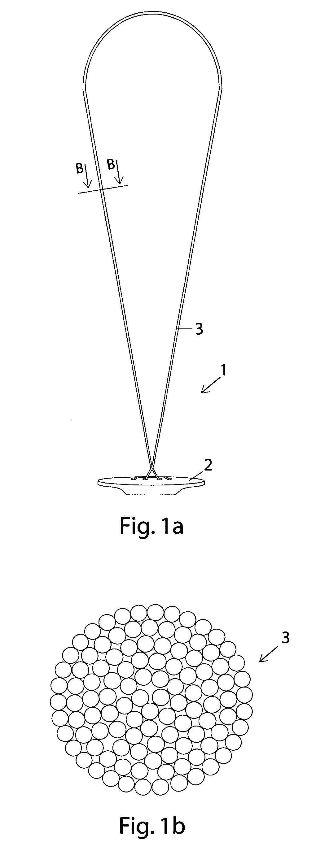
[0017]In FIG. 1a, a first embodiment of a sealing device 1 comprising an inner member 2 and retaining member 3 in the form of a loop 3 according to the present invention is schematically illustrated. The inner member 2 is adapted to be introduced into a vessel (for example, a blood vessel) and positioned at an inner surface of the vessel wall, where the inner member 2 is held in place by tension applied in the retaining member 3. The retainer loop 3 has been created by winding up a thin filament multiple times such that the loop 3 has several coils of the same filament. Depending on in particular the surface characteristics of the filament used, the number of windings can easily be made sufficiently large such that a loop that holds together without the use of, for example, a knot or glue is produced. To prevent any tendency of the filament coils to fray, an adherent, like wax or suture coating, can be applied to the surface of the filament during winding. As an alternative, an adherent could be applied to the surface of the loop after the loop has been produced. Such an adherent can also enhance the friction characteristics of the filament surface, such that fewer turns are needed to create a loop that reliably holds together.
[0018]FIG. 1b illustrates very schematically a cross-section of the loop 3 shown in FIG. 1a. The cross-section of FIG. 1b, which is taken at B-B in FIG. 1a, is only intended to show that in a cross-section of a loop according to the first embodiment of the present invention, the same filament appears multiple times, in this case over hundred times. By providing multiple coils of the same filament, a loop which reliably holds together can thus be provided without using any knotting or gluing techniques.

Example

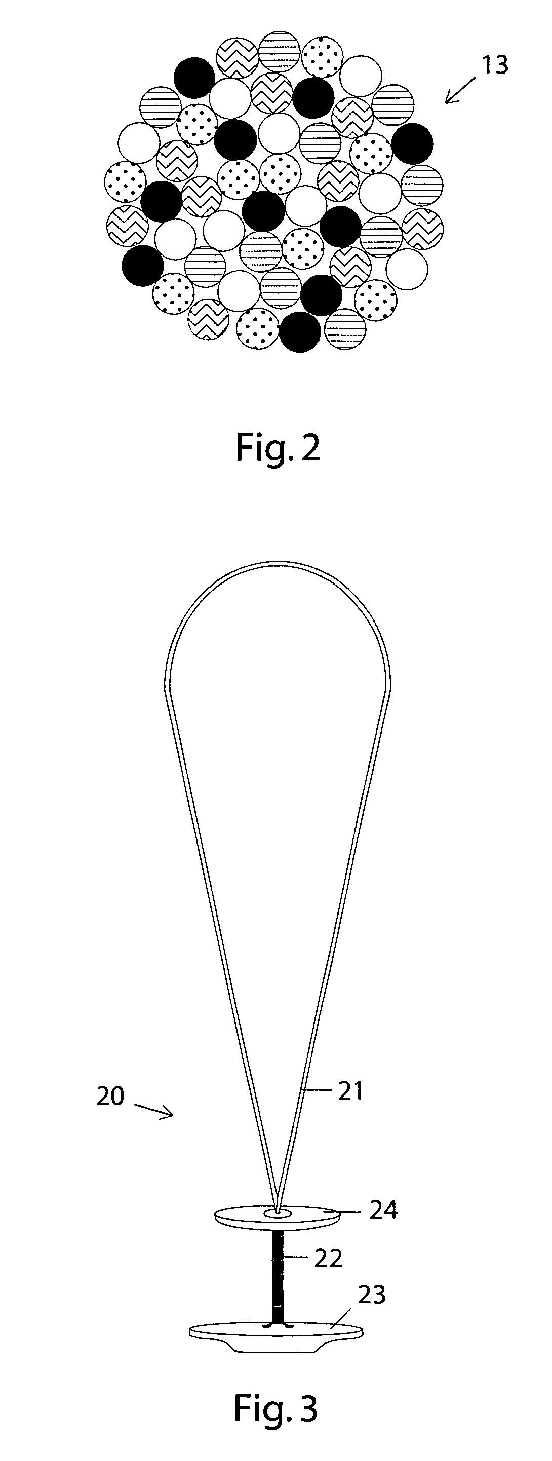
[0019]In FIG. 2 a cross-section of a second embodiment of a loop 13 according to the present invention is schematically illustrated. In this embodiment, several monofilaments have simultaneously been wound multiple times to create a composite loop 13. For illustrating purposes the number of monofilaments has been reduced to five (5), and the number of turns is ten (10), resulting in that each monofilament appears ten times in the cross-section and that the cross-section comprises a total of fifty (50) individual monofilament cross-sections. In practise, it may be preferred that these numbers, for example, are doubled, i.e. the number of monofilaments is ten (10) and the number of coils is twenty (20). It should, however, be emphasized that for a given situation, the adequate number of monofilaments as well as the adequate number of turns are very easily established by a few simple trials.
[0020]A similar way of manufacture a loop comprising multiple coils of the same filaments is to wind a multifilament multiple times. A multifilament consists of several filaments, which, for example, have been braided or twined into a multifilament. Also in this case, the result of the winding process is that a cross-section of the loop comprises several individual filament cross-sections, i.e. very similar to the cross-section shown in FIG. 2. In a test it was demonstrated that by winding a multifilament several times and thus providing a loop comprising several coils of the same filaments, the resulting loop would rather break than be drawn apart when large tension was applied. The test data is summarized in Table 1 below.
Maximum tension applied Number of to loop (Newton) just prior coils to failure Mode of failure 2 4.3 Sliding 4 11.5 Break 8 33.5 Break 20 79.0 Break 30 108.1 Break
[0021]Table 1 shows the test results for a multifilament braided from twenty (20) filaments made from a segmented copolymer composed of L,L-lactide, trimethylene carbonate and ε-caprolactone with the weight percentage 88:8:4 and made by Poly-Med, Inc., South Carolina, U.S. The multifilament was wound into loops consisting of different numbers of coils. Each loop was then subjected to tension, and the maximum tension (in Newton) before failure as well as mode of failure were recorded. To prevent any unravelling tendencies of the loops, an adherent in the form of ordinary hair wax (Sportin' Waves® sold by Soft Sheen Products, Inc., Illinois, U.S.) was applied to the surface of the loops. As evident from Table 1, when the multifilament was wound only two (2) times, the mode of failure was sliding, whereas already four (4) windings produced a loop which instead broke. Herein, the failure mode “break” indicates that the filaments themselves break apart, while the failure mode “sliding” indicates that the filaments slide readily with respect to one another such that the loop unravels. The term “readily” is meant to distinguish this catastrophic unravelling of the filaments in a loop from a small and insignificant (initial) displacement or rearrangement of the filaments in a loop. Such a displacement or rearrangement can typically occur at the start of the tensioning of the loop in question.
[0022]The general purpose of a loop according to the invention is to function as a retaining member in a sealing device, wherein the retaining member holds an inner member. When the sealing device further comprises an outer member, which can slide along the retaining member until it is to be held in place by a friction lock created between the retaining member and a bore or hole in the outer member, a loop according to the invention can preferably be provided with a thickened portion. This thickened portion is advantageously also provided as a knotless portion in that one or several filaments are wound around a portion of a loop already created in accordance with the method described above. The windings of this thickened portion are thus directed perpendicular to the windings (or coils) of the basic loop. Alternatively, the transverse coils of a thickened portion can be made by winding of at least one filament which is not a continuous part of a filament forming the basic longitudinal loop.
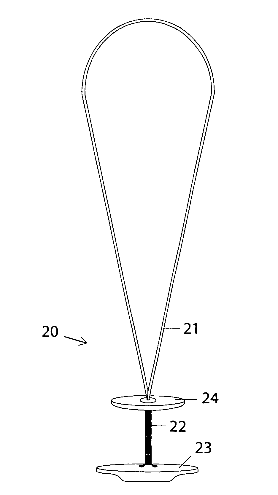
[0023]Such a thickened portion is disclosed in FIG. 3, where a loop 21 is provided with a thickened portion 22 is schematically illustrated. A corresponding sealing device 20 can consequently comprise a retaining member 21 in the form of the loop 21 with the thickened portion 22, an inner member 23, which is connected to the retaining member 21, and an outer member 24, which is slidably attached to the retaining member 21 by a bore, which has been made through the outer member 24 and through which the loop 21 has been threaded. When the sealing device 20 is positioned at a vessel wall in order to stop bleeding through a puncture hole made therein, the inner member 23 is first positioned at an inner surface of the vessel wall, and then the outer member 24 is slid along the retaining member 21 until it is pushed up and over the thickened portion 22 into contact with an outer surface of the vessel wall, such that the inner member 23 and the outer member 24 sandwich the vessel wall and the outer member 24 is held in place by friction acting on the thickened portion 22 of the loop 21 and the bore made in the outer member 24, to thereby seal the puncture hole made in the vessel wall. As should be appreciated from FIG. 3, the thickened portion 22 has been created by multiple winding of at least one filament around a portion of the basic loop 21. The number of windings around the main loop 21 can easily be increased until the thickness of the thickened portion 22 is sufficiently large to reliably hold the outer member 24 in place.
[0024]As with the first embodiment of the invention shown in FIGS. 1a and 1b, the loop 21 including the thickened portion 22 can be provided with an adherent, whose main purpose is to prevent any fraying tendencies of the filaments constituting the loop 21 and the thickened portion 22. Such an adherent can also enhance the friction acting between neighbouring filament coils in the loop, such that less coils are needed to provide a loop that reliably holds together.
[0025]Although the present invention has been described with reference to specific embodiments, also shown in the appended drawings, it will be apparent to those skilled in the art that many variations and modifications can be done within the scope of the invention as described in the specification and defined with reference to the claims below. It is in particular contemplated that the number of windings and thereby the number of resulting coils of a loop can range from a rather small number, e.g. five or ten, to a rather large number like several hundreds, depending on the specifics of the filament(s) used and the final strength required. A suitable number can easily be determined by a few simple experiments.

PUM

no PUM

Description & Claims & Application Information

We can also present the details of the Description, Claims and Application information to help users get a comprehensive understanding of the technical details of the patent, such as background art, summary of invention, brief description of drawings, description of embodiments, and other original content. On the other hand, users can also determine the specific scope of protection of the technology through the list of claims; as well as understand the changes in the life cycle of the technology with the presentation of the patent timeline. Login to view more.

Similar technology patents

Classification and recommendation of technical efficacy words

  • Increase friction

Cord anchor

InactiveUS20070023149A1Increase frictionExtensible doors/windowsCurtain accessoriesWindow coveringEngineering
Owner:HUNTER DOUGLAS IND BV

Lead obstacle-crossing robot walking device

ActiveCN101574983AIncrease frictionIncrease crawl angleManipulatorCable installation apparatusHigh voltage transmission linesEngineering
Owner:CHINA ELECTRIC POWER RES INST +1
Why Eureka
Try Eureka