Movable floor system for swimming pool

a technology for moving floors and swimming pools, applied in public buildings, gymnasiums, buildings types, etc., can solve problems such as time-consuming, complicated and expensive manufacture of platforms, and drawbacks of existing systems, and achieve the effect of raising and lowering

Inactive Publication Date: 2009-09-24
JURACEK FREDERIC
View PDF14 Cites 13 Cited by
  • Summary
  • Abstract
  • Description
  • Claims
  • Application Information

AI Technical Summary

Problems solved by technology

However, the existing systems have certain drawbacks.
In the first place, the manufacture of the platforms is complicated and expensive because of the large number of different parts that have to be assembled.
Consequently the number of transverse elements is very large, hence requiring time and adding to the complexity of producing such a mesh.
A pushing or pulling system of this kind is usually voluminous, and its installation at the bottom of the swimming pool makes for a not-insignificant loss of volume of the part of the cavity that can actually be used as a swimming pool.
However, such a device has the drawback of being heavy and requiring a large amount of energy to raise it.
Another drawback is its structure, comprising two superimposed layers, making it voluminous, cumbersome and expensive.

Method used


Image

  • Movable floor system for swimming pool
  • Movable floor system for swimming pool
  • Movable floor system for swimming pool

Examples


Embodiment Construction

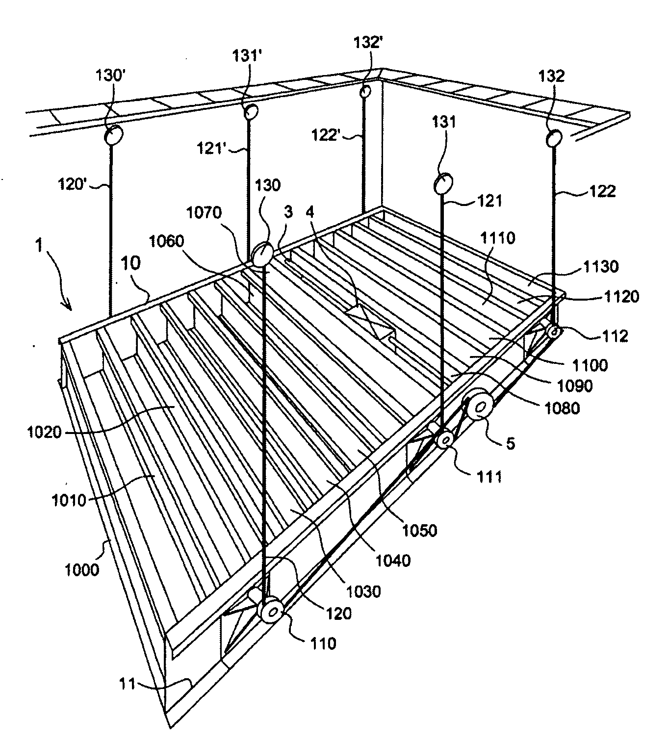
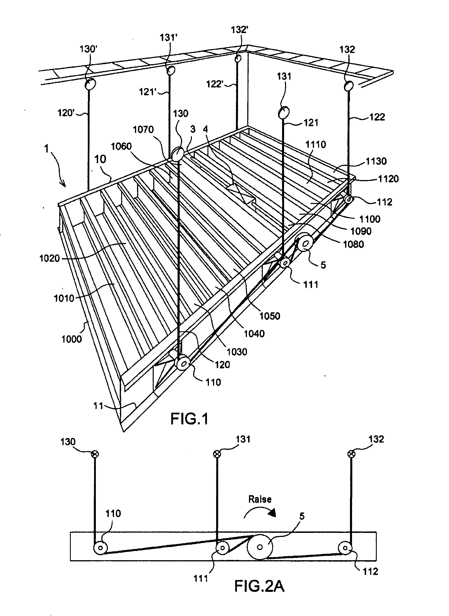
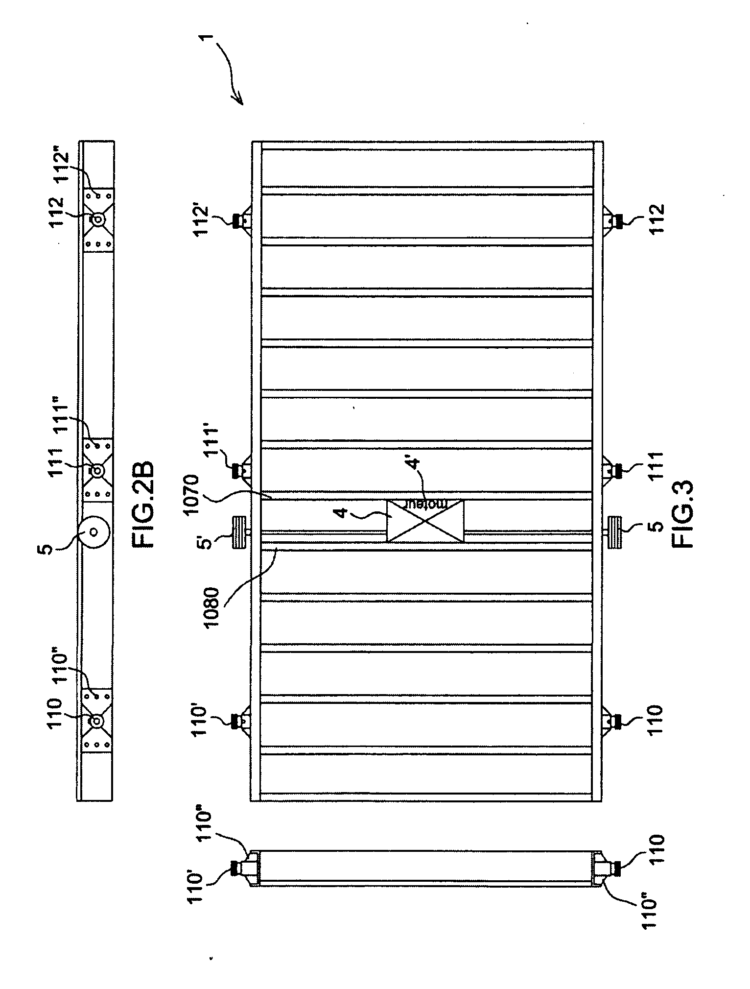
[0042]The movable floor 1 according to the invention is shown in one embodiment in FIG. 1. It comprises in this embodiment a structure comprising two lateral beams 10, 11 and a plurality of mutually parallel crossmembers 1000, 1010, 1020, 1030, 1040, 1050, 1060, 1070, 1080, 1090, 1100, 1110, 1120, 1130. The two crossmembers 1000, 1130 each positioned at one end of the structure form the frame of the structure with the lateral beams 10, 11. The space between two consecutive crossmembers is preferably from forty to fifty centimetres.

[0043]The movable floor according to an embodiment of the invention comprises a shaft 3 and a motor 4. The latter may be a winch type motor. The motor 4 drives the shaft 3 and the latter runs through the lateral beams 10, 11 in such a way as to be fixed to two pulleys 5, 5′, one at each end of the shaft. These pulleys are called the “drive pulleys” in the rest of this description, although the drive function of the system is provided by the motor 4 and by ...


PUM


Abstract

A movable floor system for a swimming pool, including a structural platform comprising a horizontal frame designed to support a finished covering, the platform being designed to be installed in a cavity acting as the swimming pool. The system includes a lifting mechanism, a plurality of parallel crossmembers fixed within a layer formed by the frame of the platform; and a plurality of carrier pulleys located along outer lateral edges of the frame, the carrier pulleys designed to accommodate a platform-driving cable. The lifting mechanism further includes: a driver; a shaft; first and second drive pulleys situated at the ends of the shaft designed to take at least one platform-driving cable; an attachment to secure at least one cable in the cavity; and means for actuating the drive shaft.

Description

CROSS-REFERENCE TO RELATED APPLICATION[0001]The present application claims the benefit to French Patent Application Serial No. 0851760, filed Mar. 19, 2008, which is hereby incorporated by reference in its entirety.TECHNICAL FIELD[0002]The present invention relates to movable floor systems for swimming pools. More specifically it relates to a movable floor system designed to be installed in cavities initially used as a swimming pool. The field of the invention applies to cavities, usually water-filled, designed either as indoor swimming pools or equally as outdoor swimming pools.[0003]The system according to the invention allows the cavity to be used notably in two ways, with the movable floor raised or lowered, corresponding to a closed position and an open position, respectively, of the cavity.[0004]In the open position the movable floor is on the floor of the cavity and the cavity can therefore be used as a swimming pool. In the closed position the movable floor is joined to the ...

Claims


Application Information

Patent Timeline
Patent Type & Authority Applications(United States)
IPC IPC(8): E04H4/00
CPCE04H4/065E04H4/06
Inventor JURACEK, FREDERIC
Owner JURACEK FREDERIC
Why Eureka
Try Eureka