
Water sensitive variable counterweight device driven by osmosis

a counterweight device and water sensitive technology, applied in the direction of fluid removal, borehole/well accessories, sealing/packing, etc., can solve the problems of reducing the amount and quality of oil produced, unsatisfactory conditions

Inactive Publication Date: 2009-09-24
BAKER HUGHES INC
View PDF96 Cites 42 Cited by
  • Summary
  • Abstract
  • Description
  • Claims
  • Application Information

AI Technical Summary

Benefits of technology

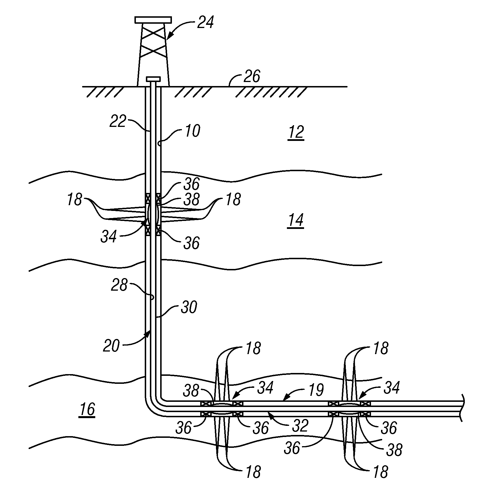
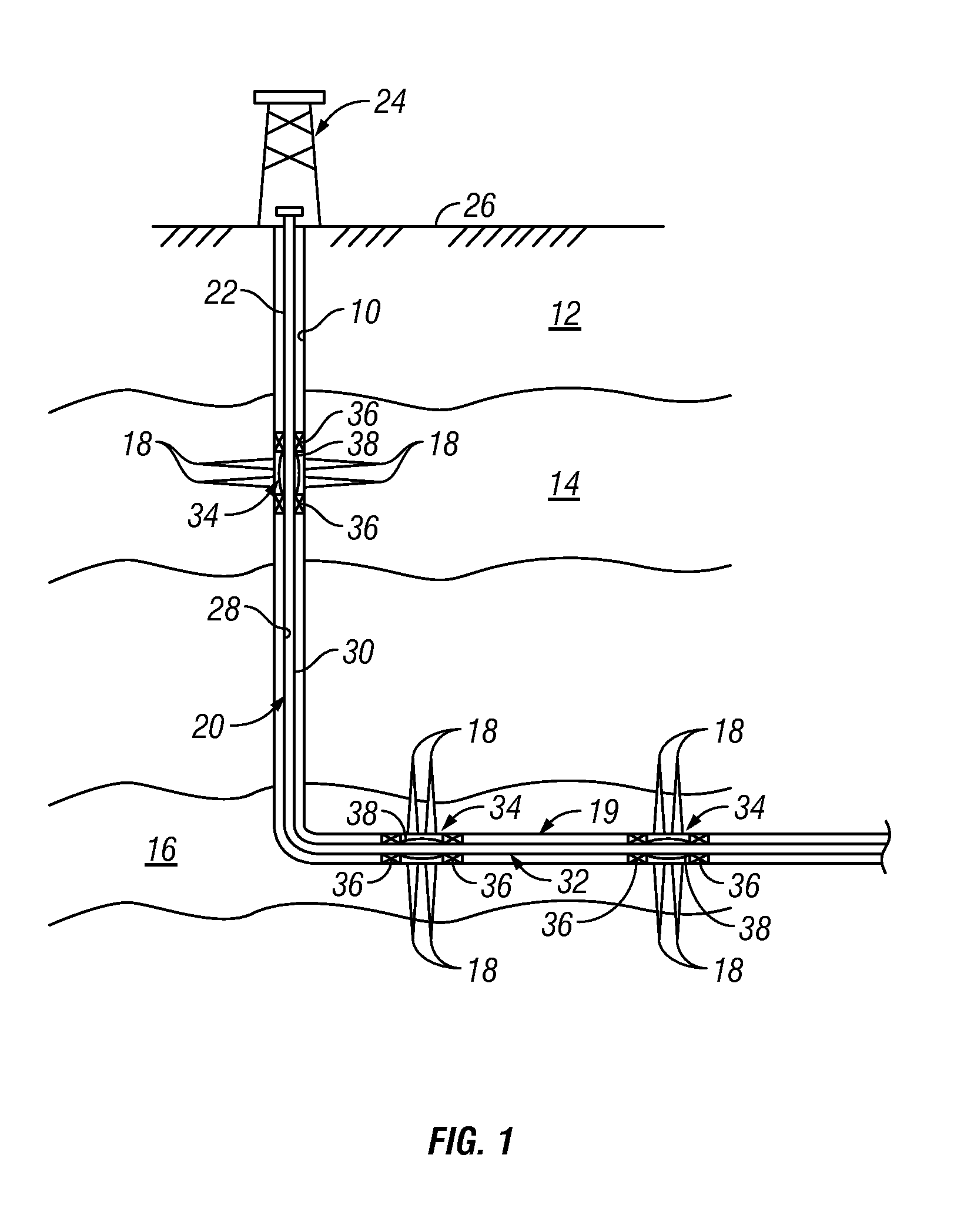
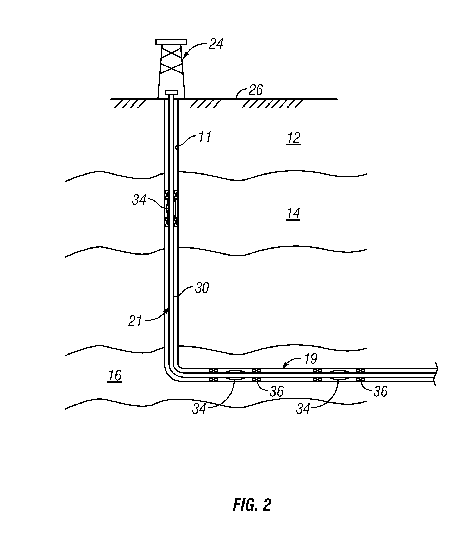
[0009]In aspects, the present disclosure provides a system for controlling a flow of a fluid in a well intersecting a formation of interest. The system may include a tubular configured to be disposed in the well; a flow restriction element positioned at a selected location along the tubular, the flow restriction element being configured to control flow between a bore of the tubular and the exterior of the tubular; and an actuator coupled to the flow restriction element. The actuator may include a selectively buoyant body that has an interior space and a membrane controlling fluid communication into the interior space. In aspects, a valve may be used to vent the interior space. In embodiments, the system may include a plurality of flow restriction elements positioned at selected locations along the tubular. Each flow restriction element may be configured to control flow between a bore of the tubular and the exterior of the tubular. An actuator coupled to each flow restriction element may include a selectively buoyant body having an interior space and a membrane controlling fluid communication into the interior space.
[0010]It should be understood that examples of the more important features of the disclosure have been summarized rather broadly in order that detailed description thereof that follows may be better understood, and in order that the contributions to the art may be appreciated. There are, of course, additional features of the disclosure that will be described hereinafter and which will form the subject of the claims appended hereto.

Problems solved by technology

Uneven drainage may result in undesirable conditions such as an invasive gas cone or water cone.
In like fashion, a water cone may cause an inflow of water into the oil production flow that reduces the amount and quality of the produced oil.

Method used


Image

  • Water sensitive variable counterweight device driven by osmosis
  • Water sensitive variable counterweight device driven by osmosis
  • Water sensitive variable counterweight device driven by osmosis

Examples


Embodiment Construction

[0019]The present disclosure relates to devices and methods for controlling production of a hydrocarbon producing well. The present disclosure is susceptible to embodiments of different forms. There are shown in the drawings, and herein will be described in detail, specific embodiments of the present disclosure with the understanding that the present disclosure is to be considered an exemplification of the principles of the disclosure, and is not intended to limit the disclosure to that illustrated and described herein. Further, while embodiments may be described as having one or more features or a combination of two or more features, such a feature or a combination of features should not be construed as essential unless expressly stated as essential.

[0020]Referring initially to FIG. 1, there is shown an exemplary wellbore 10 that has been drilled through the earth 12 and into a pair of formations 14, 16 from which it is desired to produce hydrocarbons. The wellbore 10 is cased by m...


PUM


Abstract

A method for producing fluid from a subterranean formation includes configuring a body to at least partially fill with a selected fluid; and actuating a flow restriction element using the body. The selected fluid may be water. An apparatus for controlling flow of a fluid into a wellbore tubular may include a selectively buoyant body, and a flow restriction element responsive to a movement of the selectively buoyant body. The selectively buoyant body includes a membrane configured to block a flow of hydrocarbons into the selectively buoyant body. The flow restriction element may include a flapper, a sliding sleeve, and a poppet valve. The body may be at least partially filled with a permeable material, which includes, but is not limited to, open-cell foam, reticulated metal foam, shaped sintered powder and capillary tubes.

Description

CROSS-REFERENCE TO RELATED APPLICATIONS[0001]noneBACKGROUND OF THE INVENTION[0002]1. Field of the Invention[0003]The invention relates generally to systems and methods for selective control of fluid flow into a wellbore.[0004]2. Description of the Related Art[0005]Hydrocarbons such as oil and gas are recovered from a subterranean formation using a wellbore drilled into the formation. Such wells are typically completed by placing a casing along the wellbore length and perforating the casing adjacent each such production zone to extract the formation fluids (such as hydrocarbons) into the wellbore. These production zones are sometimes separated from each other by installing a packer between the production zones. Fluid from each production zone entering the wellbore is drawn into tubing that runs to the surface. It is desirable to have substantially even drainage along the production zone. Uneven drainage may result in undesirable conditions such as an invasive gas cone or water cone. ...

Claims


Application Information

Patent Timeline
Patent Type & Authority Applications(United States)
IPC IPC(8): E21B33/12
CPCE21B33/124E21B34/08E21B43/32E21B43/12E21B43/14E21B43/08
Inventor GUEST, RANDALL V.CROW, STEPHEN L.CORONADO, MARTIN P.
Owner BAKER HUGHES INC
Learn More