Method and apparatus for controlling gas injection in process chamber

a technology of process chamber and process gas injection, which is applied in the direction of lighting and heating apparatus, combustion types, dental surgery, etc., can solve the problems of process non-uniformities (, non-uniform deposition or etching rate), non-uniformities on the substrate being processed,

Inactive Publication Date: 2009-09-24
APPLIED MATERIALS INC
View PDF60 Cites 23 Cited by
  • Summary
  • Abstract
  • Description
  • Claims
  • Application Information

AI Technical Summary

Benefits of technology

[0008]In another aspect of the invention, methods for processing a substrate are provided. In some embodiments, a method for processing a substrate may include distributing a process gas or gas mixture to a process chamber via a plurality of gas inlets having independent control of the gas flow therethrough; and controlling a gas flow of the process gas or gas mixture through each gas inlet. In some embodiments, a flow rate at one or more gas inlets is different than a flow rate at one or more different gas inlets. In some embodiments, the composition of a process gas mixture provided to one or more of the plurality of inlets may be independently controlled. In some embodiments, the plurality of gas inlets may be grouped into at least two zones of gas inlets, each zone having at least one gas inlet. The gas flow of the process gas or gas mixture may be controlled differently in a first zone of the at least two zones than in a second zone of the at least two zones. In some embodiments, a gas flow may be provided through one or more of the plurality of gas inlets that has a gas flow direction that is different than at least one of the remaining ones of the plurality of gas inlets.

Problems solved by technology

The inventors have observed that, in conventional process chambers that utilize a single flow rate controller to controller the flow rate of all process gases entering the process chamber, process non-uniformities (for example, non-uniform deposition or etch rates) exist that are believed to be due, at least in part, to non-uniform flow of process gases entering the process chamber.
Further, it has been observed that even within process chambers having uniform gas flows, processing conditions for various processes may still lead to non-uniformities developing on a substrate being processed.

Method used


Image

  • Method and apparatus for controlling gas injection in process chamber
  • Method and apparatus for controlling gas injection in process chamber
  • Method and apparatus for controlling gas injection in process chamber

Examples


Embodiment Construction

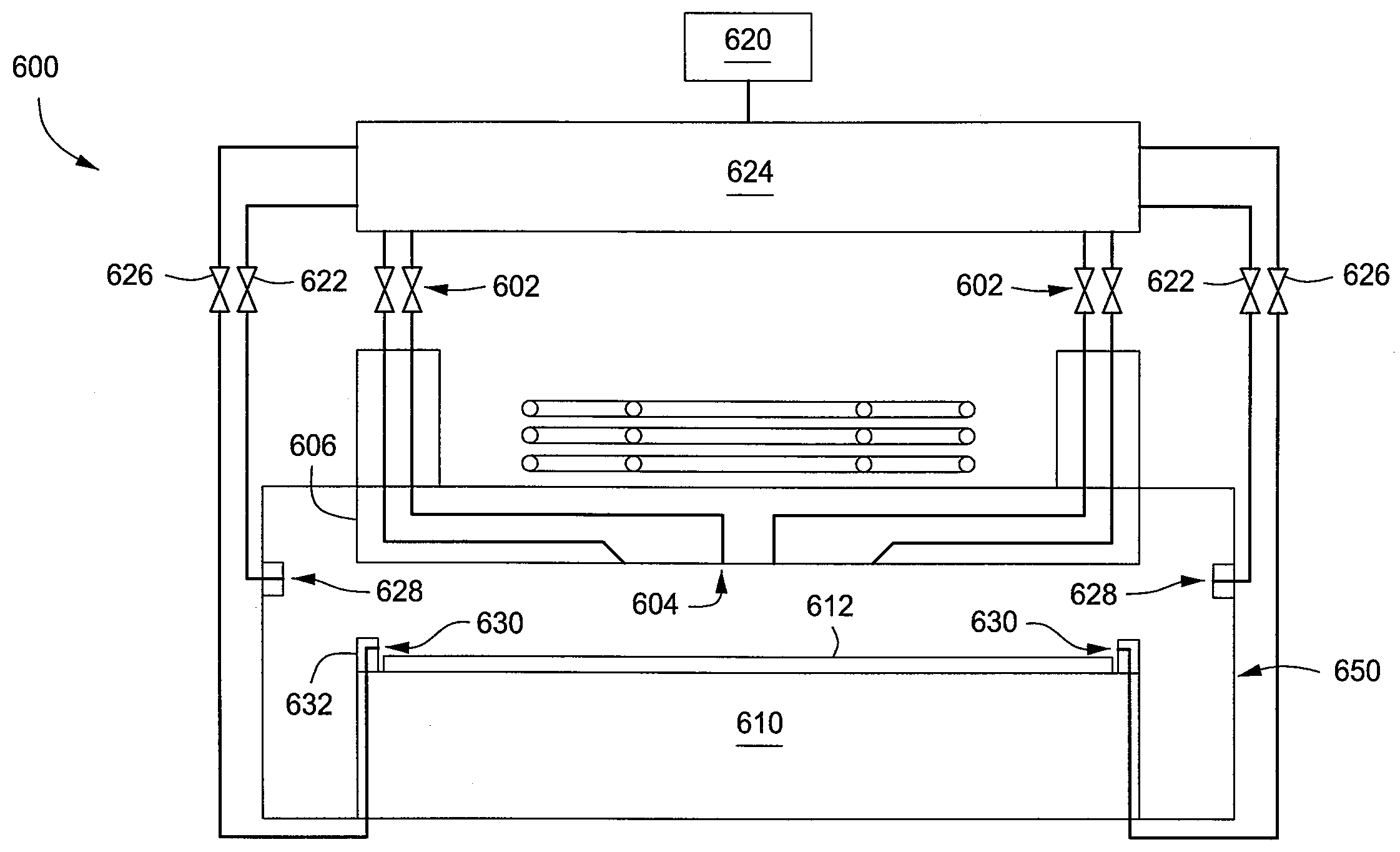
[0019]Embodiments of the present invention provide methods and apparatus for processing substrates having improved gas distribution control. In some embodiments, a process chamber may be provided having an improved gas distribution system for the injection of process gases into the process chamber. The improved gas distribution system facilitates providing a more controlled gas flow and / or more controlled distribution of process gases proximate the surface of a substrate disposed within the process chamber. Such controlled flow and distribution of process gases proximate the surface of the substrate may facilitate processing of the substrate as desired. In some embodiments, the controlled flow and distribution of process gases may be more uniform. In some embodiments, the controlled flow and distribution of process gases may be provided to facilitate more uniform processing of the substrate. It is contemplated that other, non-uniform processing profiles may also be obtained using th...


PUM

PropertyMeasurementUnit
flow rateaaaaaaaaaa
angleaaaaaaaaaa
compositionsaaaaaaaaaa

Abstract

Methods and apparatus for processing substrates are provided herein. In some embodiments, a gas distribution apparatus may include a plurality of gas inlets configured to deliver a process gas to a process chamber; and a plurality of flow controllers having outlets coupled to the plurality of gas inlets for independently controlling the flow rate through each of the plurality of gas inlets. The gas distribution apparatus may be coupled to a process chamber for controlling the delivery of one or more process gases thereto.

Description

BACKGROUND[0001]1. Field[0002]Embodiments of the present invention generally relate to semiconductor processing, and more particularly, to methods and apparatus for controlling process gas injection in a process chamber.[0003]2. Description of the Related Art[0004]As the critical dimensions for semiconductor devices continue to shrink, there is an increased need for semiconductor process equipment that can uniformly process semiconductor substrates. One instance of where this need may arise is controlling the flow of process gases proximate the surface of a substrate disposed in a process chamber. The inventors have observed that, in conventional process chambers that utilize a single flow rate controller to controller the flow rate of all process gases entering the process chamber, process non-uniformities (for example, non-uniform deposition or etch rates) exist that are believed to be due, at least in part, to non-uniform flow of process gases entering the process chamber. Furthe...

Claims


Application Information

Patent Timeline
Patent Type & Authority Applications(United States)
IPC IPC(8): B05B1/14H01L21/306C23C16/00
CPCC23C16/45565H01J37/32449H01J37/3244C23C16/45574
Inventor PANAGOPOULOS, THEODOROSPATERSON, ALEXANDERHOLLAND, JOHN P.KATZ, DANHAMMOND, IV, EDWARD P.
Owner APPLIED MATERIALS INC
Why Eureka
Try Eureka