Bipedal walking robot

Inactive Publication Date: 2009-09-24
HONDA MOTOR CO LTD
View PDF22 Cites 15 Cited by
  • Summary
  • Abstract
  • Description
  • Claims
  • Application Information

AI Technical Summary

Benefits of technology

[0011]The present invention has been accomplished in view of the aforementioned problems, and therefore a first object of the present invention is to provide a bipedal walking robot capable of applying a desired moment to a foot without increasing a linear (translatory) actuator in size, and a second object thereof is to improve motion performance of the bipedal walking robot by decreasing moments of inertia of a thigh link and a crus link.

Problems solved by technology

However, this will make the foot driving linear (translatory) actuator extend greatly to the front side or rear side of the crus link, deteriorating the slim looking of the leg.

Method used


Image

  • Bipedal walking robot
  • Bipedal walking robot
  • Bipedal walking robot

Examples


Embodiment Construction

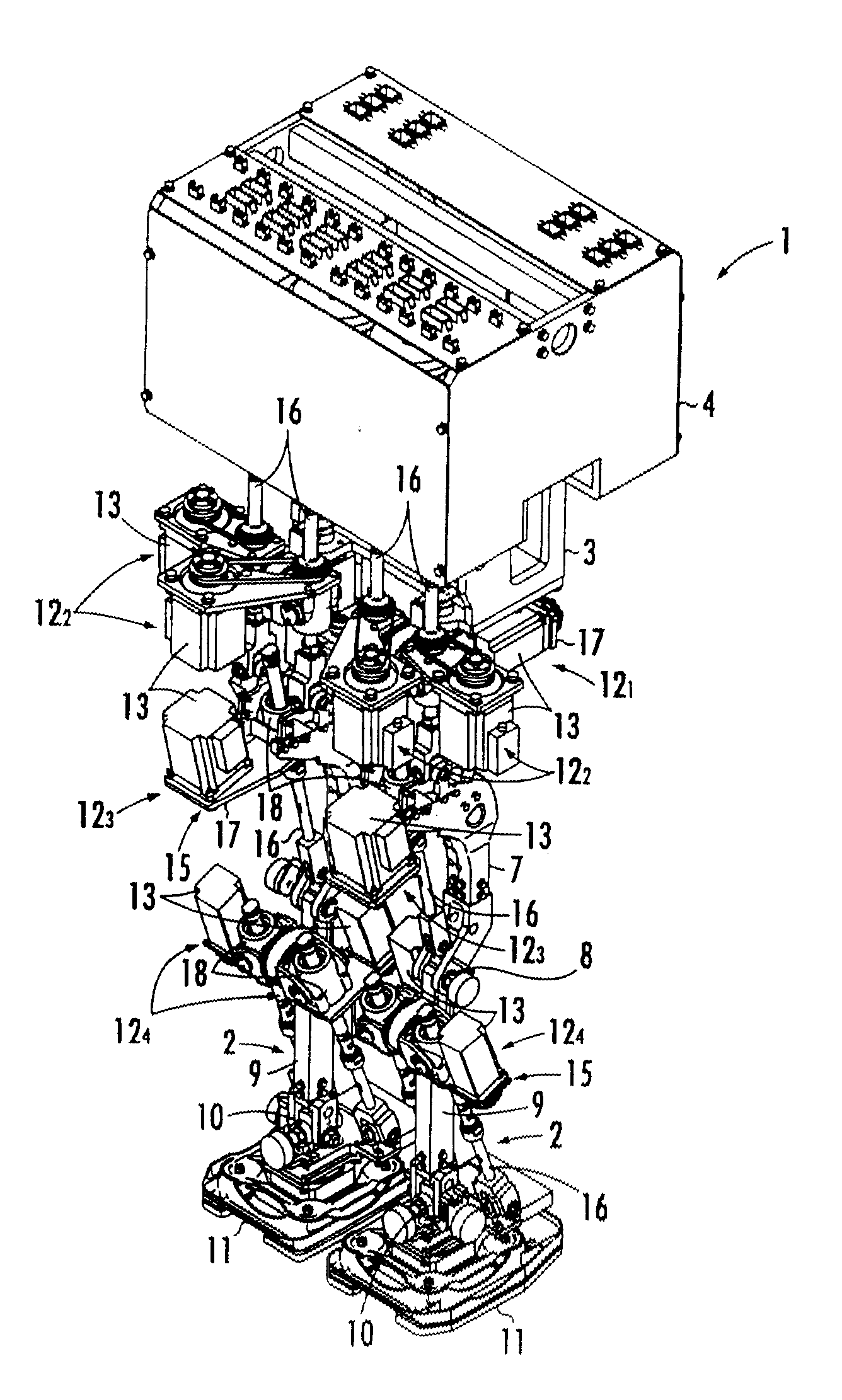
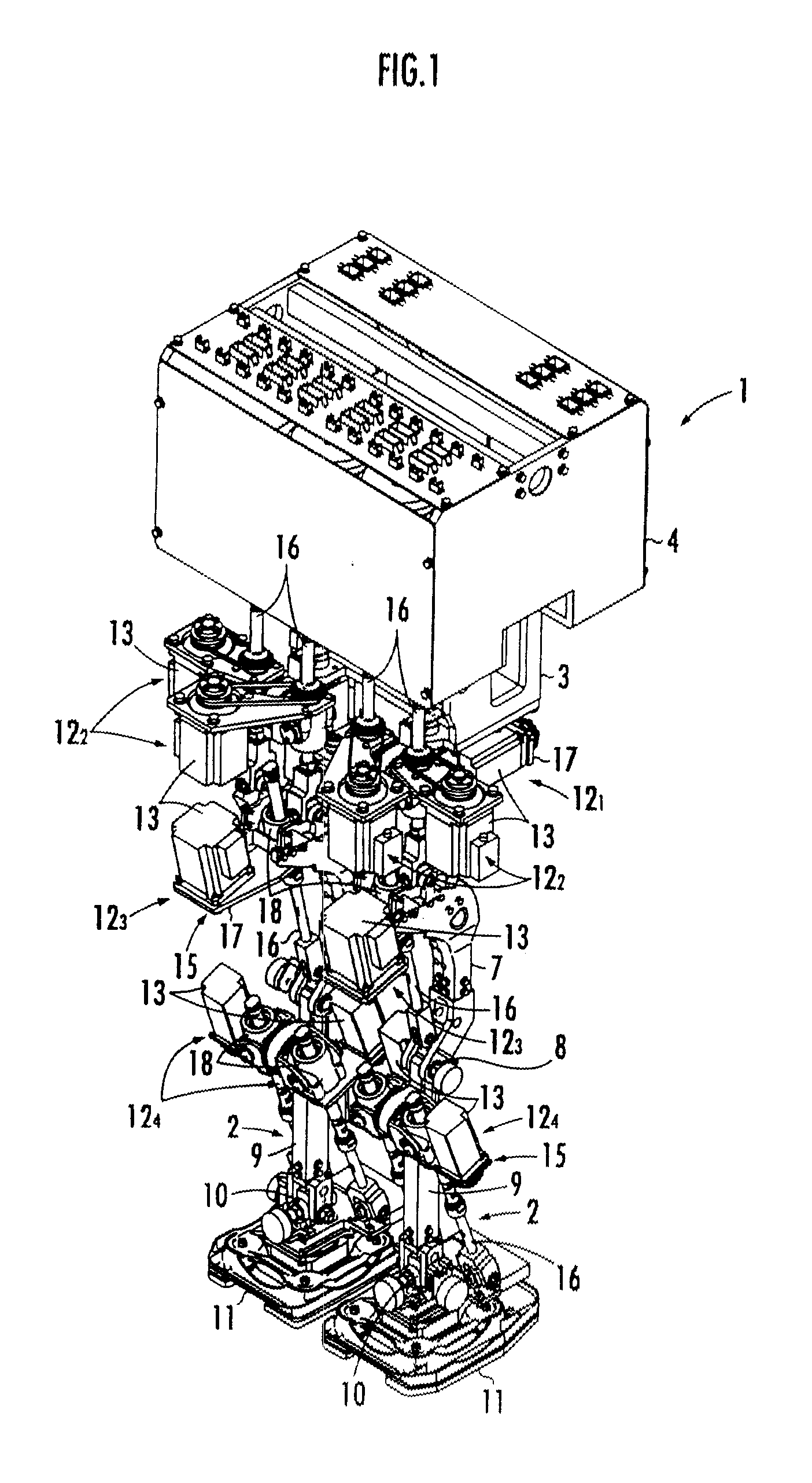
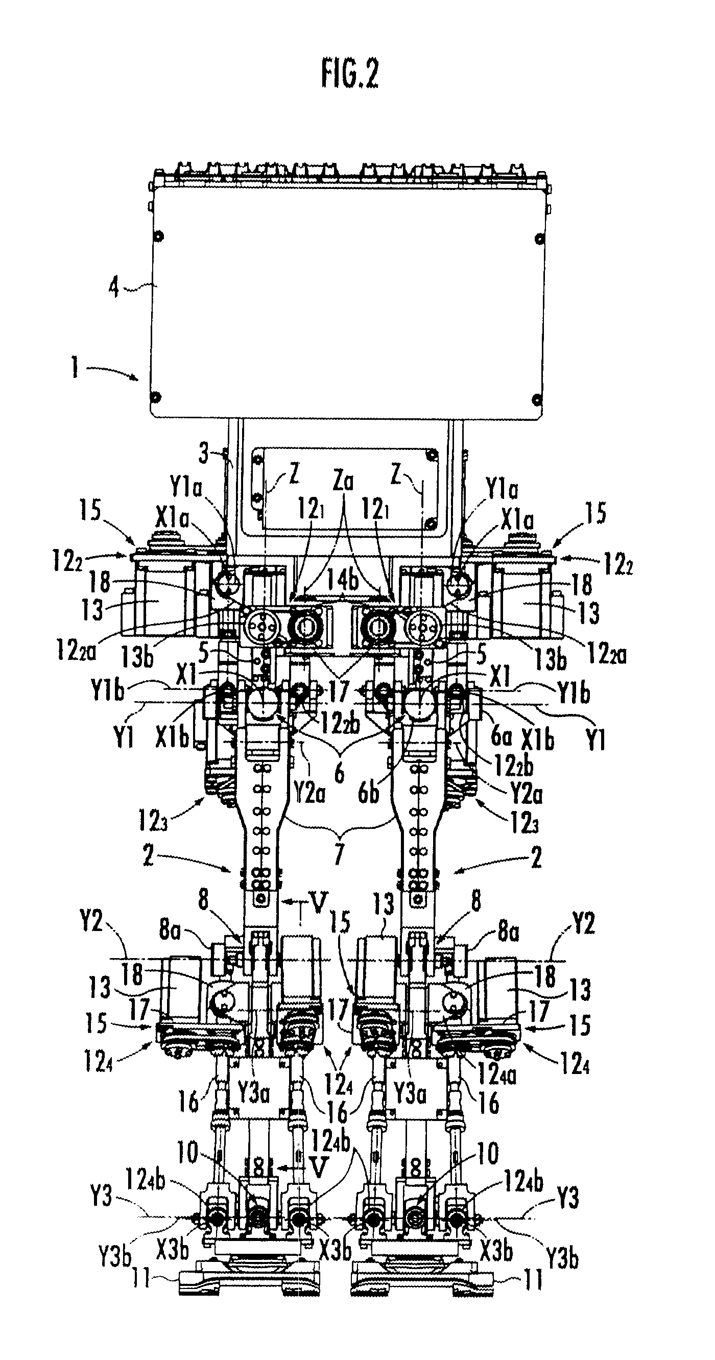
[0029]A bipedal walking robot according to an embodiment of the present invention is illustrated in FIG. 1 to FIG. 4. The bipedal walking robot includes a body 1 and a pair of legs 2 and 2 at both sides of the body 1. The body 1 is provided with a body frame 3. A control box 4 is mounted on the body frame 3. The body frame 3 is disposed side by side with a pair of rotation yokes 5 and 5 which are connected by a pair of legs 2 and 2, respectively. The rotation yoke 5 can freely rotate around a vertical axis (Z axis).

[0030]Each leg 2 is composed of a thigh link 7, a crus link 9 and a foot 11. The thigh link 7 is connected to a lower end of each rotation yoke 5 of the body 1 through a hip joint 6. The crus link 9 is connected to a lower end of the thigh link 7 through a knee joint 8. The foot 11 is connected to a lower end of the crus link 9 through an ankle joint 10.

[0031]The hip joint 6 is configured as a 2-axis joint having a rotation degree around 2 axes of a lateral axis (Y1 axis)...


PUM


Abstract

Provided is a bipedal walking robot which includes a linear actuator, which connects a crus link and a foot of each leg away from an ankle joint, for driving the foot to rock around the ankle joint with respect to the crus link according to a telescopic motion thereof. The robot is capable of applying a desired moment to the foot for walking on stairs without increasing the linear actuator in size. The linear actuator is disposed in such a way that a telescopic force therefrom acts on a line inclined backward with respect to a connection line connecting a knee joint and the ankle joint. Preferably, a connection portion, which is connected to the crus link, of the linear actuator is disposed backward from the connection line, and a connection portion, which is connected to the foot, of the linear actuator is disposed forward from the connection line.

Description

BACKGROUND OF THE INVENTION[0001]1. Field of the Invention[0002]The present invention relates to a bipedal walking robot having a body and a pair of legs at both sides of the body.[0003]2. Description of the Related Art[0004]For a bipedal walking robot having a body and a pair of legs at both sides of the body, each leg thereof is composed of a thigh link connected to the body through a hip joint, a crus link connected to a lower end portion of the thigh link through a knee joint, and a foot connected to a lower end portion of the crus link through an ankle joint. There has been conventionally known a bipedal walking robot having a crus driving linear (translatory) actuator, which connects the thigh link and the crus link of each leg away from the knee joint, for driving the crus to rock around the knee joint, and a foot driving linear (translatory) actuator, which connects the crus link and the foot of each leg away from the ankle joint, for driving the foot to rock around the ankl...

Claims


Application Information

Patent Timeline
IPC IPC(8): B25J5/00
CPCB62D57/032
Inventor TAKENAKA, KENJIMATSUOKA, YOSHIHISAICHIHASHI, SATORU
Owner HONDA MOTOR CO LTD
Why Eureka
Try Eureka