Legged Robot

a robot and leg technology, applied in the field of legs, can solve the problems of large distance in the pitch direction between the center of mass of the trunk and the leg, and achieve the effects of reducing load and moment, preventing an increase in moment, and large step length

Inactive Publication Date: 2009-01-08
TOYOTA JIDOSHA KK
View PDF18 Cites 12 Cited by
  • Summary
  • Abstract
  • Description
  • Claims
  • Application Information

AI Technical Summary

Benefits of technology

[0027]Due to having the features described above, it is possible to realize a legged robot that, in addition to preventing an increase in the moment that is generated due to the gravitational force that acts on the trunk and acts on the roll joint of the leg that is in contact with the ground while standing only on one leg, can reduce the load and the moment acting on the leg connecting portion of the grounding leg, and can ensure a large step length while keeping the height of the trunk at a low position.
[0028]Preferably each of the legs is connected to the trunk vertically above the center of mass of the trunk when viewed from the lateral direction (the pitch direction). Due to such a configuration, it is possible to put the attitude of the trunk around the rotation axis of the leg connecting portion to an auto-stabilizing state. Specifically, even in a state in which the trunk and the legs can freely rotate, due to the gravitational force, the center of mass of the trunk is positioned vertically below the rotation axis of the leg connecting portions. Even in a state in which the trunk and legs can rotate freely, the trunk does not overturn. It is possible to stabilize the attitude of the trunk around the rotation axis of the leg connecting portions.
[0029]Preferably, the trunk has a seat, and the seat base of the seat is positioned vertically below the connecting portions (leg connecting portions) when viewed from the lateral direction (the pitch direction). Generally, it is known that when a person is seated, the position of the center of mass of the person is located in the vicinity of the hip. Therefore, it is possible to keep the position of the center of mass of a seated rider below the rotation axis of the leg connecting portions by positioning the seat base of the seat to be below the leg connecting portions. When taken into consideration along with the fact that the rotation axis of the leg connecting portions is positioned above the position of the center of mass of the trunk, it is possible to make the position of the center of mass of the trunk and the rider to be below the rotation axis of the leg connecting portions. It is possible to stabilize the attitude of the trunk in which a rider is riding.
[0030]According to the present invention, a legged robot that can walk with long strides while maintaining the height of the trunk at a low position, and suppress an increase of the load acted upon the roll joint of the grounding leg while standing with only one grounding leg is achieved.

Problems solved by technology

However, if the legs are connected to the lateral surfaces of the trunk, the distance in the pitch direction between the center of mass of the trunk and the legs becomes large.
When the moment that acts around the roll axis in the leg becomes large, the actuators of the roll joints possessed by the leg are burdened with further load that counteract the moment.

Method used


Image

  • Legged Robot
  • Legged Robot
  • Legged Robot

Examples


first embodiment

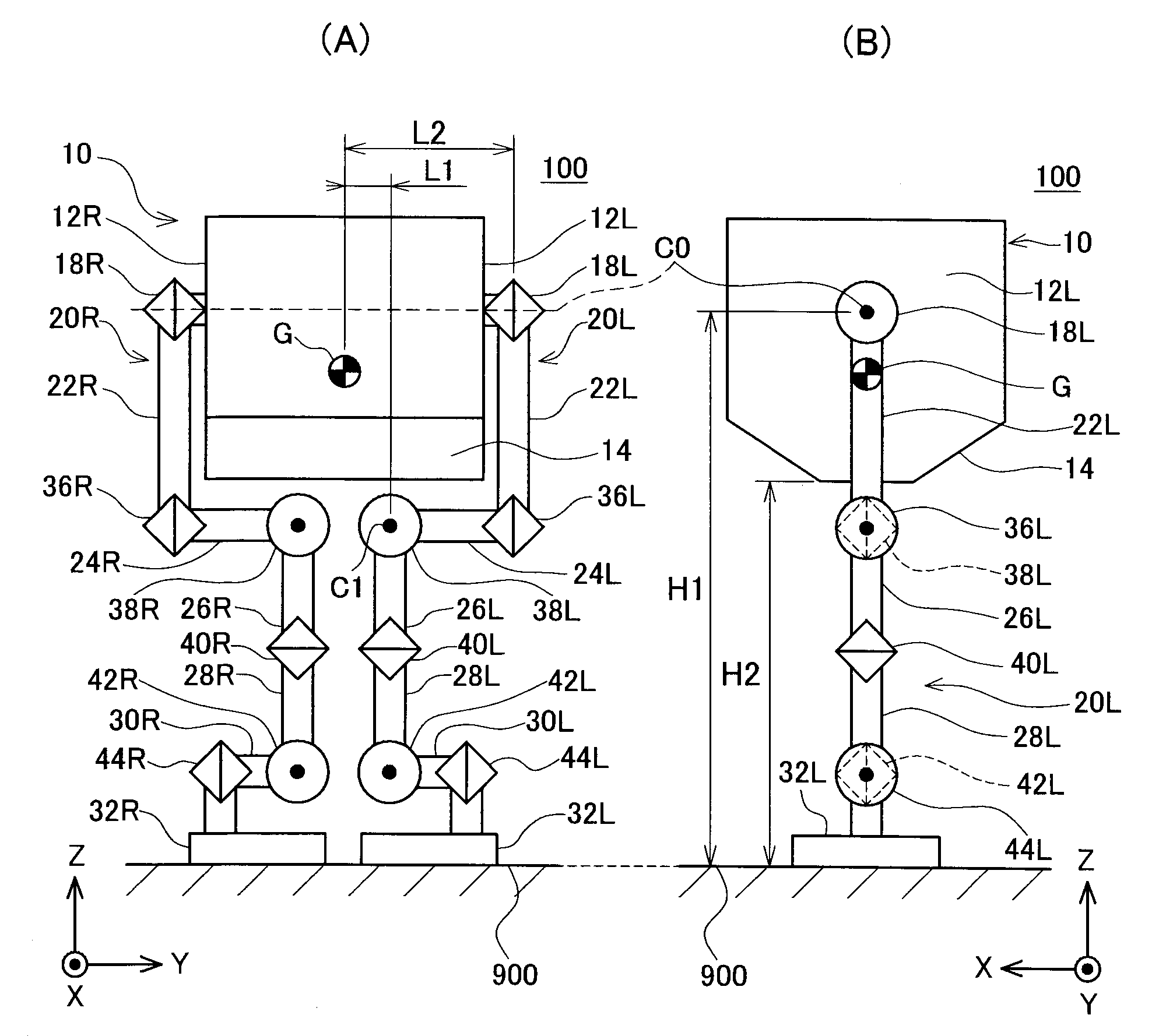
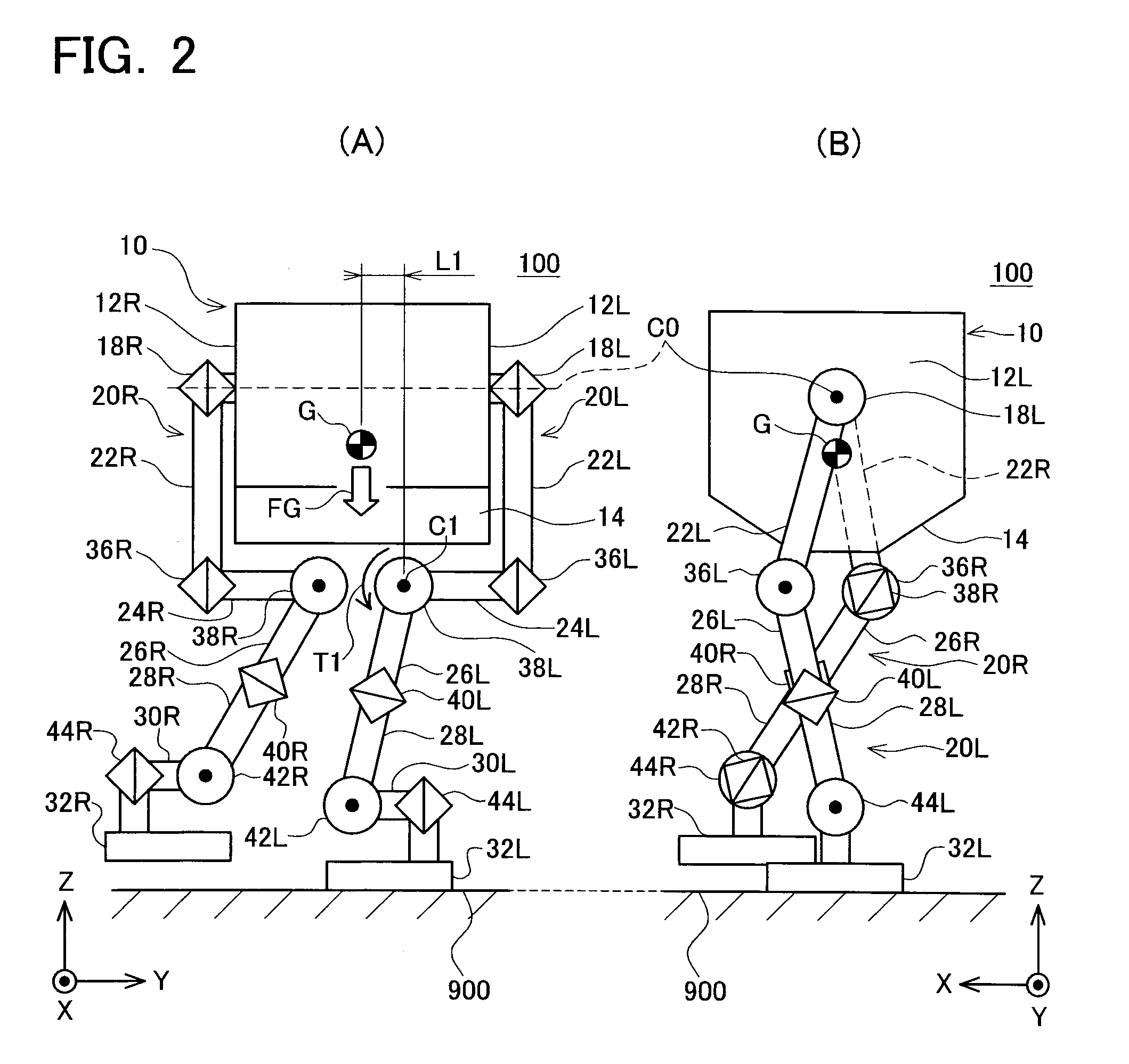
[0039]The legged robot according to the first embodiment of the present invention will be explained with reference to FIGS. 1(A) to 2(B). FIG. 1(A) is a front view of the legged robot 100. FIG. 1(B) is a side view of the legged robot 100. The legged robot 100 includes a trunk 10 and a pair of legs 20L and 20R. Note that in FIG. 1(B), the illustrations of parts that are hidden by the parts that are positioned to the front side of the figure are omitted except for the parts shown by the reference numerals 38L and 42L.

[0040]First, the coordinate system will be explained. In FIG. 1(A) and FIG. 1(B), an XYZ coordinate system defines a right-handed orthogonal coordinate system. This XYZ coordinate system has an origin that is fixed to the trunk 10 of the legged robot 100. The X-axis extends forward from the trunk 10 of the legged robot 100. The X-axis is referred to as the roll axis. The Y-axis extends along the lateral direction of the trunk 10 of the legged robot 100. The Y-axis is refe...

second embodiment

[0072]Next, the second embodiment will be explained with reference to FIGS. 3(A) and 3(B). A legged robot 200 according to the second embodiment has a trunk 210 and a pair of legs 220L and 220R. FIG. 3(A) is a front view of the legged robot 200 in a state in which the right leg 220R is the free leg and the left leg 220L is the grounding leg. FIG. 3(B) is a side view that corresponds to FIG. 3(A). In FIG. 3(B), except for a right first link 222R, the illustrations of the parts hidden by the parts that are positioned to the front of the figure are omitted.

[0073]The differences between the legged robot 200 and the legged robot 100 shown in FIG. 1(A) are the shape of a bottom surface 214 of the legged robot 200 and that the legs 220L and 220R of the legged robot 200 each have rollers 16L and 16R. The other aspects are identical to those of the legged robot 100 shown in FIG. 1(A), and thus the detailed explanation thereof has been omitted. Note that except for the numbers in the third di...

third embodiment

[0081]Next, a third embodiment will be explained with reference to FIG. 4. FIG. 4 is a side view of a legged robot 300 according to the third embodiment. The legged robot 300 has a trunk 310, a pair of legs 320L and 320R, and a pair of leg connecting portions 318L and 318R. The explanation of the pair of legs 320L and 320R will be omitted because they are identical to the pair of legs 20L and 20R that are provided on the legged robot 100 of the first embodiment. The pair of legs 320L and 320R may be identical to the pair of legs 220L and 220R that are provided on the legged robot 200 of the second embodiment. The explanation of the pair of leg connecting portions 318L and 318R is omitted because they are identical to the pair of leg connecting portions 18L and 18R that are provided on the legged robot 100 of the first embodiment.

[0082]In the side view of FIG. 4, with respect to the pair of legs 320L and 320R, the illustration of the parts that cannot be seen due to parts that are po...


PUM


Abstract

A legged robot that can ensure a large step length while keeping the height of a body trunk at a low position without increasing a moment that is generated due to the gravitational force acting on the trunk and acting on roll joints of legs when standing on one leg is realized. In the legged robot, a pair of legs is connected so as to be able to rotate around a pitch axis (Y-axis) at lateral surfaces of a trunk. Thereby, it is possible to make the height H1 high while keeping the height of the trunk low. It is possible to ensure a large step length while keeping the height of the trunk at a low position. Legs have a structure in which roll joints are positioned below a bottom surface. Thereby, the length L1 in the pitch axis direction between the rotation axis C1 of these joints and the center of mass G of the trunk is limited. The moment acting on the roll joints of the grounding leg when standing on one leg is not increased.

Description

CROSS-REFERENCE TO RELATED APPLICATION[0001]This application claims priority to Japanese Patent Application No. 2006-055319, filed on Mar. 1, 2006, the contents of which are hereby incorporated by reference into this specification.TECHNICAL FIELD[0002]The present invention relates to a legged robot. In particular, the present invention relates to a legged robot that can walk with long strides while keeping the height of the body trunk at a low position, and that does not increase the load applied to one of the legs when standing only with the one of the legs.[0003]In the present specification, the roll direction, the pitch direction, and the yaw direction, which are mutually perpendicular, are defined as follows. In a perpendicular coordinate system fixed to the body trunk of the robot, the direction that extends forward from the body trunk is defined as the roll direction. The direction that extends vertically upward from the body trunk is defined as the yaw direction. The directio...

Claims


Application Information

Patent Timeline
Patent Type & Authority Applications(United States)
IPC IPC(8): B25J5/00
CPCB62D57/032B25J5/00Y10S901/01
Inventor SUGA, KEISUKEYAMAOKA, MASAAKI
Owner TOYOTA JIDOSHA KK
Why Eureka
Try Eureka