Gas pump with pressure relief for reducing the starting torque

a gas pump and starting torque technology, applied in the field of pumps, can solve the problems of high drive torque, dangerous delivery device, and relatively quick delivery

Active Publication Date: 2022-11-22
SCHWABISCHE HUTTENWERKE AUTOMOTIVE CMBH
View PDF31 Cites 0 Cited by
  • Summary
  • Abstract
  • Description
  • Claims
  • Application Information

AI Technical Summary

Benefits of technology

[0006]It is an object of the invention to reduce the forces or moments acting on a delivery device of a gas pump when the gas pump is started, in a way which is cost-effective, reliable and simple in design, and advantageously without the solution in accordance with the invention impairing the delivery rate of the pump.
[0008]In order to reduce the forces or moments acting on the delivery device when the gas pump is started, the second housing part can be moved relative to the first housing part, against a pressing force with which the two housing parts are pressed against each other in the region of the sealing join, in such a way that the sealing join can be widened. Widening the sealing join forms a relieving gap through which liquid situated in the delivery chamber, such as in particular lubricating fluid, can escape. The pressing force is generated by means of a pressing device which presses the sealing surfaces of the two housing parts against each other. The pressing device is configured such that the pressing force of the pressing device is reached when a maximum pressure which prevails in the delivery chamber and acts on the second housing part is reached, and the pressing force of the pressing device is exceeded when the pressure in the chamber increases further, such that the widening movement of the second housing part and the associated widening of the sealing join begins. The maximum pressure is determined by the pressing device. The pressing device can be configured such that said widening movement proceeds gradually in accordance with a positive pressure which prevails in the delivery chamber relative to the outside environment of the housing parts, or abruptly when a predefined maximum positive pressure is exceeded. The relieving gap which is formed in this way can correspondingly be gradually or abruptly closed again when the pressure in the delivery chamber is reduced, and the sealing join can thus be restored by the pressing force of the pressing device.
[0013]If the sealing join opens liquid situated in the delivery chamber escapes through the relieving gap preferably into the environment of the gas pump from where the liquid can for example flow into a reservoir for the liquid. In such embodiments the relieving gap connects the delivery chamber with the environment of the gas pump or a reservoir for the liquid. The relieving gap so to say short circuits the delivery chamber to the environment of the gas pump or the liquid reservoir. In embodiments in which the liquid is a lubricating oil for a combustion engine e.g. the motor oil for lubricating an internal combustion motor, the relieving gap connects the delivery chamber with the lubricant sump or motor oil sump of the engine or motor, the motor preferably being a drive motor for driving a vehicle. Because of the connection with the environment or the liquid reservoir, into which the liquid from the delivery chamber can escape, power losses are reduced. There is no power wasted for feeding the excess liquid, for example in a circular motion around a pump rotational axis if the gas pump is a rotary pump.
[0014]In preferred embodiments, the pressing device generates a spring force which forms at least a part of the pressing force. The pressing device can generate the whole of the pressing force as a spring force. In principle, however, embodiments can also be realised in which the pressing device only generates a part of the pressing force as a spring force and generates the remaining part in another way, for example by means of an electric or hydraulic drive. Generating the pressing force in the form of a spring force, however, enables embodiments of the pressing device which are simple in design, cheap and particularly functionally reliable. On the other hand, the possibility of the pressing device generating the pressing force not as a spring force but rather only in another way, such as for example electrically or hydraulically, should not be excluded. Such embodiments, however, have the disadvantage that the second housing half has to be actively moved in order to widen the sealing join by means of the pressing device. The spring force of the pressing device acts counter to the widening of the sealing join and thus acts as a restoring force which closes the relieving gap when the pressure in the delivery chamber abates, either in combination with an additional force applied in another way by the pressing device or preferably on its own.
[0015]If the pressing device generates at least a part of the pressing force as a spring force, it is advantageous if the pressing device is elastically flexible over a spring path which is at least as large as a maximum gap width of the relieving gap. This applies both to embodiments in which the pressing force is generated exclusively as a spring force, as is preferred, and to embodiments in which the pressing device applies a spring force in combination with an additional force in order to keep the sealing join closed.
[0019]The one or more spring members each comprise a spring support region and a spring coupling region. The respective spring member is supported in the spring support region and coupled to the second housing part in the spring coupling region. In the spring coupling region, it preferably acts on the second housing part in the direction of the pressing force. In embodiments which are simple in design and not least for this reason preferred, it acts directly on the second housing part in the spring coupling region. It can thus for example press directly against the second housing part, preferably in the direction of the pressing force. In principle, however, it is also possible to realise an indirect coupling. If indirectly coupled, the spring member acts on the second housing part via one or more transmission elements, preferably with no deflecting element. In its spring support region, the respective spring member can be supported externally in relation to the gas pump. In its spring support region, however, the respective spring member can in particular be supported on the first housing part, as applicable on a third housing part of the gas pump if one is provided. In an embodiment which is simple and not least for this reason preferred, the respective spring member is supported directly on the first housing part, such that the support does not require any transmission element but rather only a corresponding support engagement and preferably simultaneously also a holding engagement, directly from the spring member and first housing part. In alternative embodiments, the respective spring member can be supported on the first housing part via an additional fastening element such as for example a screw element or extrusion bolt element. Such embodiments are also expedient.

Problems solved by technology

In particular when the negative pressure pump is arranged in the oil sump, though in principle also when it is arranged differently, the problem exists that when the engine is started and within about the first half-revolution of the negative pressure pump, the engine oil—which is particularly viscous at this time—has to be delivered relatively quickly from the delivery chamber of the negative pressure pump.
This results in high drive torques of the negative pressure pump, such that there is a danger of the delivery device, for example a vane of the negative pressure pump, being destroyed or otherwise damaged by being overloaded or of damage being caused in the drive train of the negative pressure pump.
A comparable problem results when a negative pressure pump which is filled with oil is rotated backwards, for example when an automobile with its engine switched off rolls backwards from a car transporter when the transporter is being unloaded, and the vehicle which is still rolling is slowed by putting the switched-off engine in gear.
Said provisions do however have the disadvantage either that they are associated with additional design outlay and therefore cost for the negative pressure pump or that the evacuating rate and therefore the effectiveness of the pump are reduced.
Given the constraint of equal evacuating rates, a reduction in the effectiveness of the pumps is synonymous with an increase in the drive rates for the negative pressure pumps, resulting in a rise in the fuel consumption and correspondingly the CO2 emissions of the vehicles.

Method used


Image

  • Gas pump with pressure relief for reducing the starting torque
  • Gas pump with pressure relief for reducing the starting torque
  • Gas pump with pressure relief for reducing the starting torque

Examples


Embodiment Construction

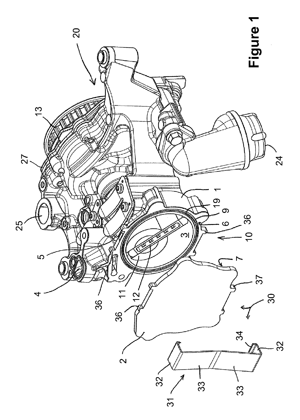
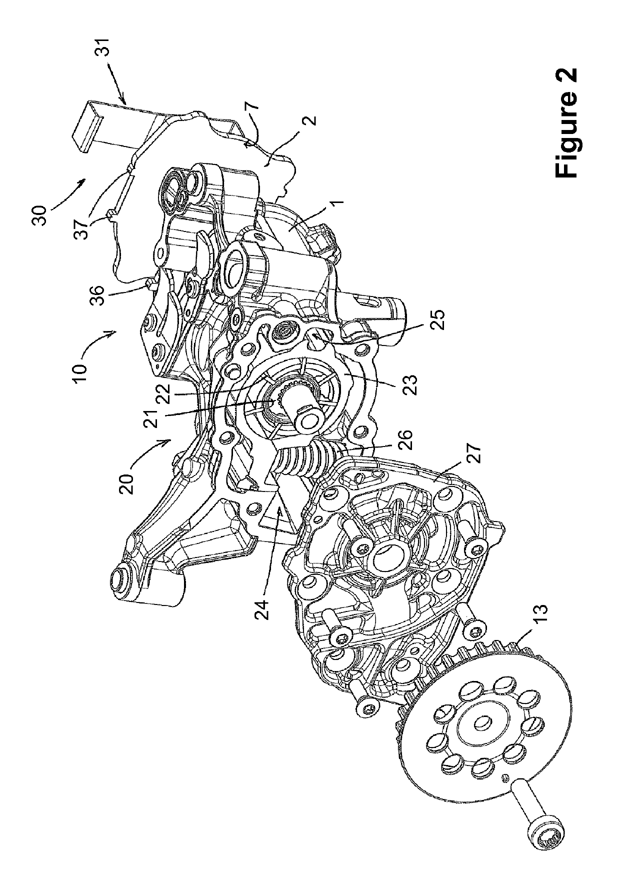
[0051]FIG. 1 shows a pump unit comprising a gas pump 10 of a first example embodiment and a liquid pump 20, in an isometric view onto the gas pump 10. The pump unit comprises a housing which is common to both pumps 10 and 20. Such arrangements of pumps are also referred to as a tandem arrangement. The common housing comprises: a housing part 1 which mounts moving components of the pump unit, in particular a delivery device of the gas pump 10 and a delivery device of the liquid pump 20, such that they can be moved; a housing part 2 which forms a cover of the gas pump 10; and a housing part 27 which forms a cover of the liquid pump 20. The housing part 1 is formed—expediently, cast—in one piece. In principle, however, it can instead also be joined from a plurality of pieces. The housing parts 2 and 27 are each formed from metal in one piece and joined to the housing part 1, for example by means of a screw connection in each case, as shown.

[0052]The gas pump 10 and the liquid pump 20 a...


PUM


Abstract

A gas pump including a delivery chamber with an inlet and an outlet for a gas. The delivery chamber is at least partially enclosed by a first housing part with a first sealing surface and a second housing part with a second sealing surface. A delivery device is moveable within the delivery chamber for delivering the gas. A pressing device presses one of the housing parts against the other with a pressing force such that the sealing surfaces abut each other and together form a sealing join which at least partially surrounds the delivery chamber in order to seal off the delivery chamber. The second housing part can be moved relative to the first housing part, against the pressing force, in order to be able to widen the sealing join to form a relieving gap through which liquid situated in the delivery chamber can escape.

Description

[0001]This application claims priority to German Patent Application No. 10 2013 200 410.9, filed on Jan. 14, 2013, the contents of which are incorporated herein by reference.FIELD OF THE INVENTION[0002]The invention relates to a pump for delivering a gas which is also referred to in the following as a gas pump and can in particular be a negative pressure pump. In the case of such pumps, the invention aims to reduce forces or torques which act on the delivery device of the pump when the pump is started.BACKGROUND OF THE INVENTION[0003]Negative pressure pumps may be used in vehicles, for example, to provide negative pressure for a brake servo. The pump can be arranged laterally on the cylinder head of a vehicle engine and driven by a cam shaft of the engine, as has been typical for a long time. Due to design space restrictions and also in order to reduce the specific design size, as well as with regard to pedestrian protection and also cost, the negative pressure pump has in more rece...

Claims


Application Information

Patent Timeline
Patent Type & Authority Patents(United States)
IPC IPC(8): F04C27/02F04C15/00F04C25/02F04C28/06F04C28/26F04C18/344F04B53/16F04C18/34
CPCF04C27/02F04B53/16F04C15/0088F04C18/34F04C18/3442F04C25/02F04C28/06F04C28/265
Inventor MEINIG, UWE
Owner SCHWABISCHE HUTTENWERKE AUTOMOTIVE CMBH
Why Eureka
Try Eureka