Mobile communication system and communication control method
- Summary
- Abstract
- Description
- Claims
- Application Information
AI Technical Summary
Benefits of technology
Problems solved by technology
Method used
Image
Examples
first exemplary embodiment
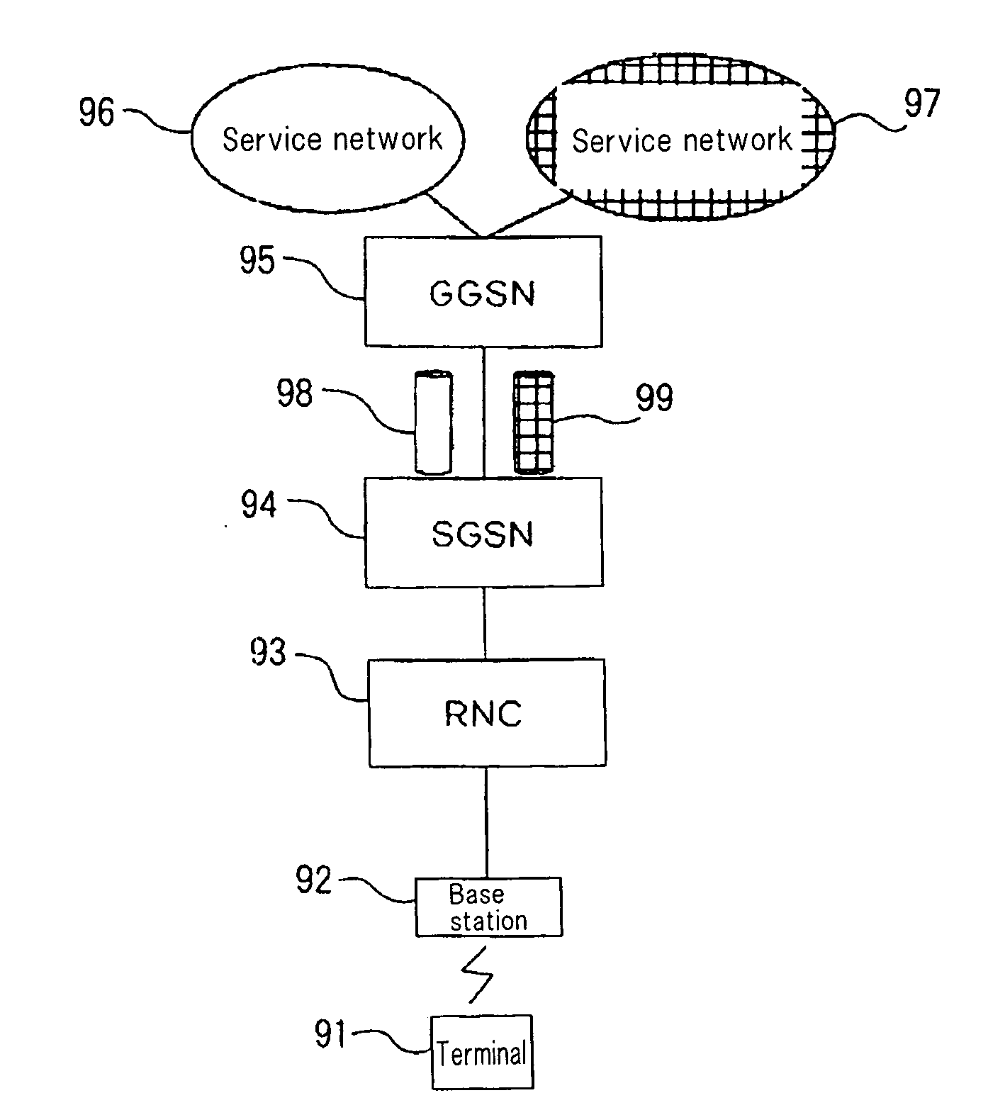
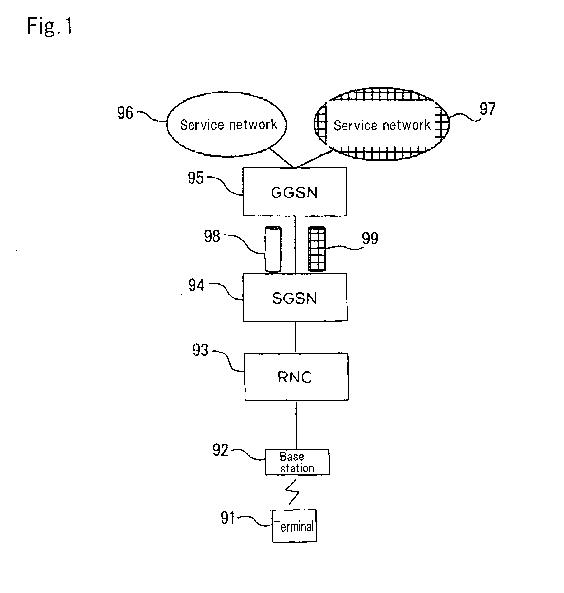
[0032]FIG. 3 is a block diagram showing a configuration of a mobile communication system according to a first exemplary embodiment. In this figure, there is shown a mobile communication system in which one terminal can be connected to a plurality of service networks at the same time.
[0033]Referring to FIG. 3, the mobile communication system has GGSN 5 (Gateway GPRS (General Packet Radio Service) Support Node), SGSN 4 (Serving GPRS Support Node), RNC 3 (Radio Network Controller), and base station 2. GGSN 5 and SGSN 4 belong to a core network, and RNC 3 and base station 2 belong to a wireless access network.
[0034]GGSN 5 is a gate device connected to two service networks 6 and 7, serves to connect the mobile communication system to service networks 6 and 7. Service networks 6 and 7 are networks which provide packet service.
[0035]SGSN 4 is a node device for providing a GPRS service, connects to RNC 2 that is connected to terminal 1, and also establishes tunnels 8 and 9 between SGSN 4 an...
second exemplary embodiment
[0048]A mobile communication system of a second exemplary embodiment can take a Direct Tunnel extended configuration which establishes GTP tunnels between an RNC and a GGSN directly. The configuration of a mobile communication system of the exemplary embodiment is the same as that of the first exemplary embodiment shown in FIG. 3. However, GTP tunnels 8 and 9 are established between RNC 3 and GGSN 5. The operation of the mobile communication system of the exemplary embodiment is the same as that of the first exemplary embodiment except for the operation of establishing the Direct Tunnel extended configuration.
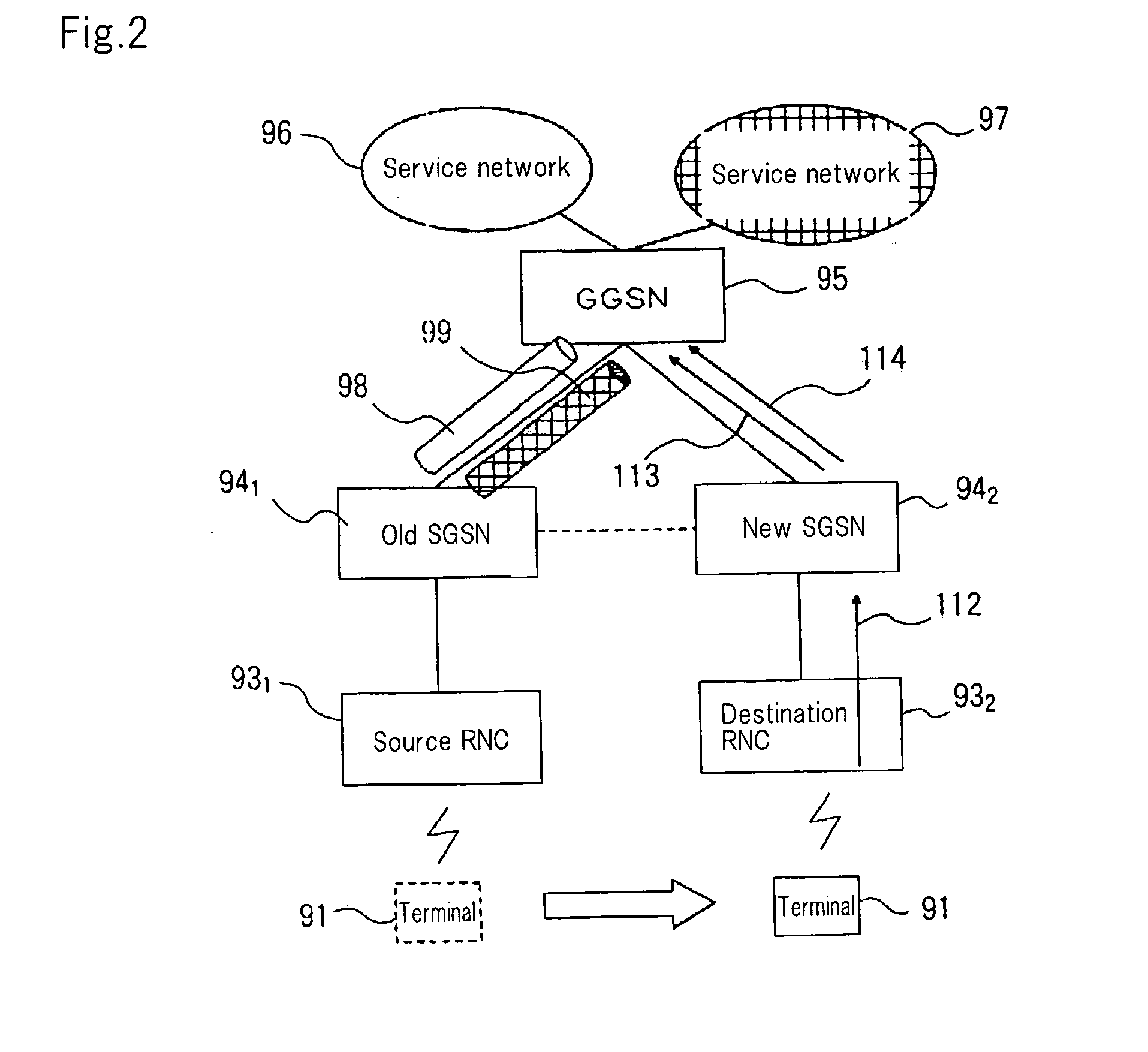
[0049]FIG. 6 is a diagram for describing an operation of a mobile communication system when terminal 1 has moved according to the second exemplary embodiment. Although, in FIG. 6, the base station is omitted for the sake of clarity, suppose that terminal 1 is connected to RNC 3 via base station 2 (not shown) as in FIG. 4. Referring to FIG. 6, terminal 1 is connected to a plural...
third exemplary embodiment
[0053]In a third exemplary embodiment, a SAE (System Architecture Evolution) system which extends the GPRS system will be exemplified.
[0054]FIG. 7 is a diagram for describing a configuration of a mobile communication system according to the third exemplary embodiment and an operation thereof when a terminal has moved. Although, in FIG. 7, the base station is omitted for the sake of clarity, suppose that terminal 1 is connected to RNC 3 via base station 2 (not shown) as in FIG. 4. Referring to FIG. 7, old SGSN 41 and new SGSN 42 are connected to serving SAE GW 31.
[0055]A mobile communication system of the third exemplary embodiment has serving SAE GW 31 and PDN SAE GWs 321 and 322, instead of GGSN 5 according to the first exemplary embodiment shown in FIG. 3. RNC 3 and base station 2 (not shown) are included in a UTRAN (Universal Terrestrial Radio Access Network), and SGSN 4, serving SAE GW 31 and PDN SAE GWs 321 and 322 are included in a core network. In the SAE system, accessing fr...
PUM
 Abstract
Description
Claims
Application Information
 - R&D
- Intellectual Property
- Life Sciences
- Materials
- Tech Scout
- Unparalleled Data Quality
- Higher Quality Content
- 60% Fewer Hallucinations
Browse by: Latest US Patents, China's latest patents, Technical Efficacy Thesaurus, Application Domain, Technology Topic, Popular Technical Reports.
© 2025 PatSnap. All rights reserved.Legal|Privacy policy|Modern Slavery Act Transparency Statement|Sitemap|About US| Contact US: help@patsnap.com


