
Location based audio reception zone system for use with vehicular entertainment systems

a technology for entertainment systems and audio reception zones, which is applied in the direction of public address systems, line-transmission, stereophonic communication headphones, etc., can solve the problems of vehicle drivers not being able to receive audio directed to driver-worn headphones, and the automotive manufacturers have no solution for this type of problem, so as to prevent a driver from being distracted and safe driving conditions

Inactive Publication Date: 2009-09-24
DELPHI TECH INC
View PDF9 Cites 1 Cited by
  • Summary
  • Abstract
  • Description
  • Claims
  • Application Information

AI Technical Summary

Benefits of technology

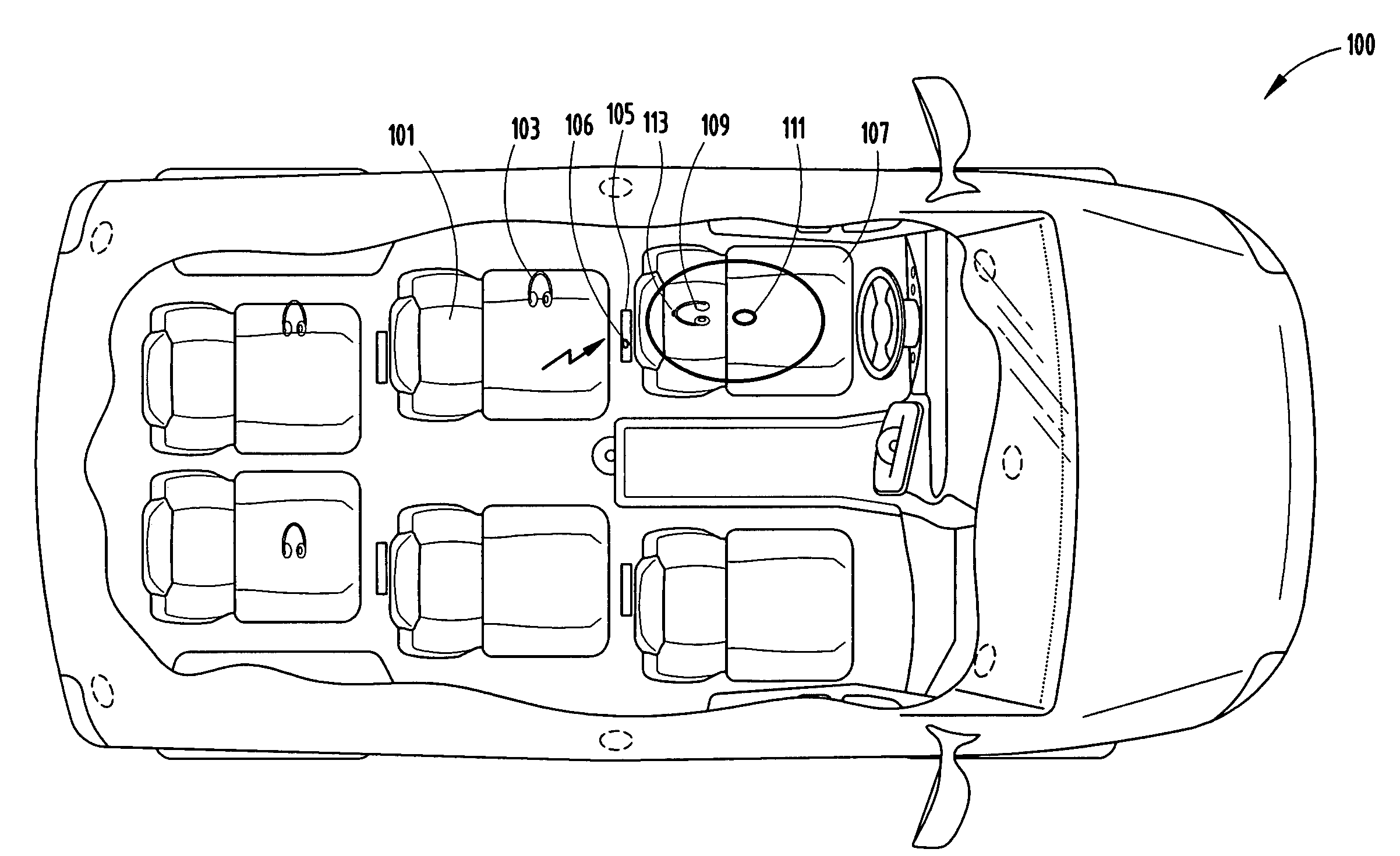
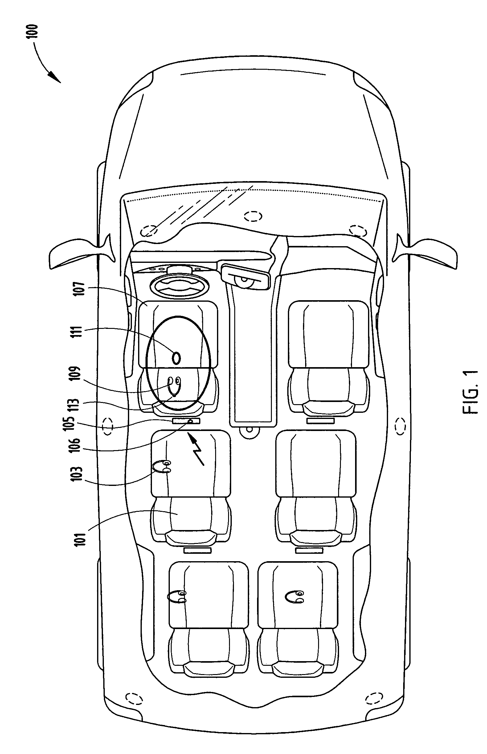
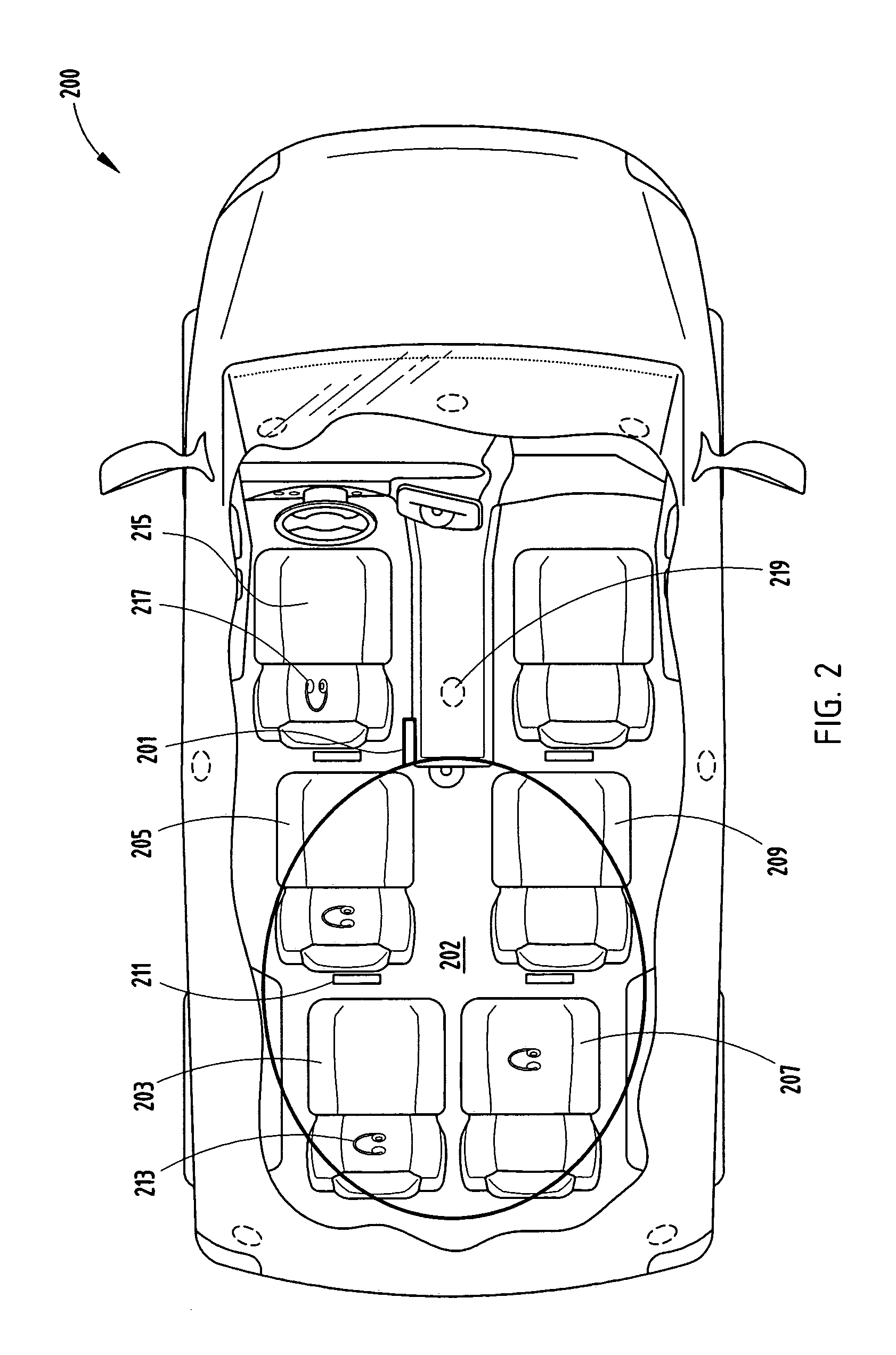
[0004]An embodiment of the present invention is directed to a location based audio reception zone system that includes a driver's seat and at least one passenger seat. A first transmitter located within the vehicle is used for broadcasting entertainment content to headsets worn by the passengers. A second transmitter also located in the vehicle is used for disabling at least one headset when the headset is located in proximity to the driver's seat. Although the first transmitter is primarily used for transmitting a radio frequency (RF) signal, the second transmitter may use an RF signal, an infrared (IR) signal, or combinations thereof. Various other techniques may be used, such as using directional antennas or locating a wire loop antenna above the driver's seat for use in disabling a headset worn by the vehicle's driver. The invention promotes safe driving conditions for preventing a driver from being distracted if wearing headsets used in connection with an onboard vehicle entertainment system.

Problems solved by technology

Due to the directional nature of the IR transmission to the headset, the driver of a vehicle is not able to receive the audio transmission while seated in the driver's seat.
However, automotive design specifications, as well as some local laws, require that the vehicle's driver not be able to receive audio directed to driver-worn headsets.
Currently, automotive manufacturers have no solution for this type of problem.

Method used


Image

  • Location based audio reception zone system for use with vehicular entertainment systems
  • Location based audio reception zone system for use with vehicular entertainment systems
  • Location based audio reception zone system for use with vehicular entertainment systems

Examples


Embodiment Construction

[0012]Before describing in detail embodiments that are in accordance with the present invention, it should be observed that the embodiments reside primarily in combinations of method steps and apparatus components related to a Faraday cage electronic enclosure. Accordingly, the apparatus components and method steps have been represented where appropriate by conventional symbols in the drawings, showing only those specific details that are pertinent to understanding the embodiments of the present invention so as not to obscure the disclosure with details that will be readily apparent to those of ordinary skill in the art having the benefit of the description herein.

[0013]In this document, relational terms such as first and second, top and bottom, and the like may be used solely to distinguish one entity or action from another entity or action without necessarily requiring or implying any actual such relationship or order between such entities or actions. The terms “comprises,”“compri...


PUM


Abstract

A location based audio reception zone system for use in vehicle includes a driver's seat and one or more passenger seats. A radio frequency (RF) transmitter is used for transmitting entertainment content to one or more headsets located in a passenger seat. The RF transmitter transmits in a predefined reception zone for disabling audio in a headset located within the zone for preventing a driver from using the headset when in the driver's seat. The invention enhances safe driving practices for preventing entertainment audio from being received by the headsets located in proximity to the driver's seat.

Description

TECHNICAL FIELD [0001]The present invention relates to automotive and / or public transportation vehicle accessories and more particularly to wireless headphones used in automotive and public transportation applications.BACKGROUND OF THE INVENTION [0002]Currently, vehicles with rear seat entertainment (RSE) units use infrared (IR) transmission for most headphone applications. Headphones are used to receive audio programming without interrupting or disturbing the driver or other passengers. Due to the directional nature of the IR transmission to the headset, the driver of a vehicle is not able to receive the audio transmission while seated in the driver's seat.[0003]In order to provide improved performance, many new headphone technologies require the use of a radio frequency (RF) link between the RSE unit and the headphone using BLUETOOTH, WiFi technologies, or the like. However, automotive design specifications, as well as some local laws, require that the vehicle's driver not be able...

Claims


Application Information

Patent Timeline
Patent Type & Authority Applications(United States)
IPC IPC(8): H04B1/20H04B1/00
CPCH04M1/6066H04M1/6091H04R2499/13H04R27/00H04R2420/07H04R5/033
Inventor BOYER, BRADLEY E.ZACKSCHEWSKI, SHAWN R.WITTENBACH, DAVID E.BISHOP, DAVID L.
Owner DELPHI TECH INC
Learn More