Microparticle delivery syringe and needle for placing particle suspensions and removing vehicle fluid

a technology of microparticles and syringes, which is applied in the direction of intravenous devices, medical syringes, syringes, etc., can solve the problem of limiting the amount of microparticles that can be delivered

Inactive Publication Date: 2009-09-24
WARSAW ORTHOPEDIC INC
View PDF15 Cites 54 Cited by
  • Summary
  • Abstract
  • Description
  • Claims
  • Application Information

AI Technical Summary

Benefits of technology

[0004]The objectives of the invention can be realized by administrating a microparticle suspension using a bifurcated syringe device having two chambers and a needle with two lumens, one lumen being fluidly connected to each chamber. One chamber of the device is filled with the microparticle suspension, while the other chamber remains empty or primed with a suitable fluid. Pushing the plunger of the chamber containing the microparticle suspension injects the suspension through one lumen of the needle and into the ...

Problems solved by technology

Such target spaces may be small and therefore may ...

Method used


Image

  • Microparticle delivery syringe and needle for placing particle suspensions and removing vehicle fluid
  • Microparticle delivery syringe and needle for placing particle suspensions and removing vehicle fluid
  • Microparticle delivery syringe and needle for placing particle suspensions and removing vehicle fluid

Examples


Embodiment Construction

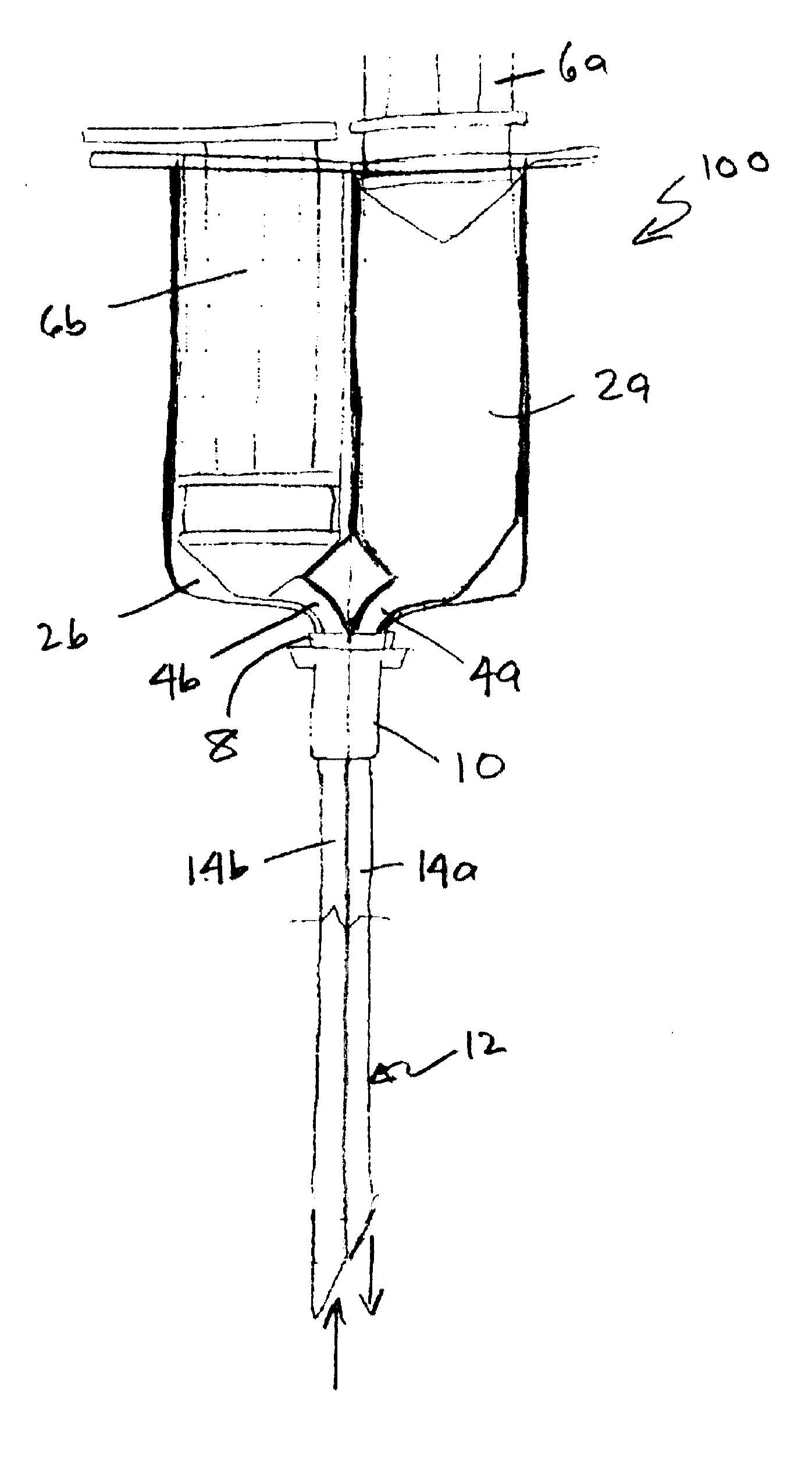
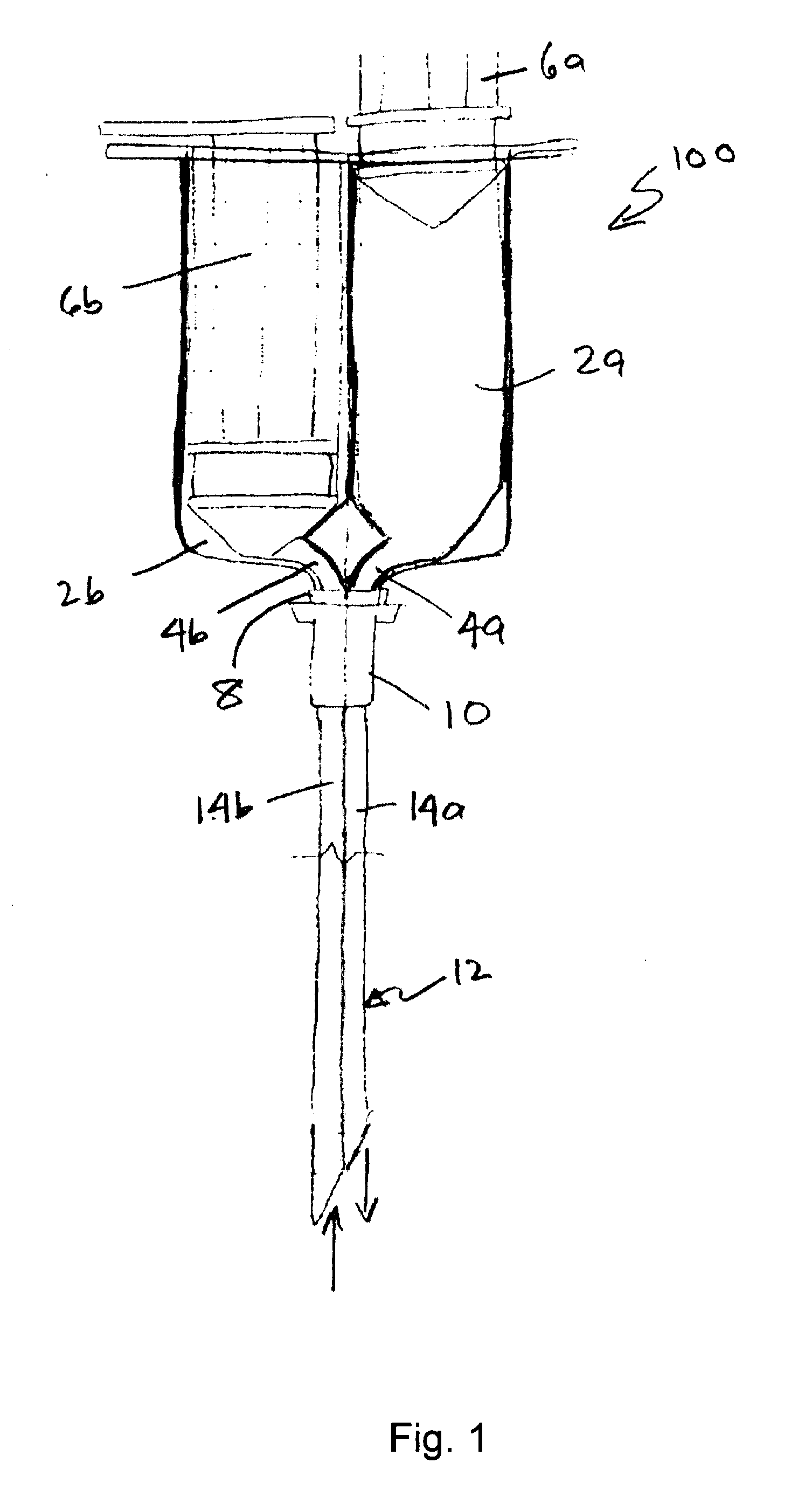
[0018]An embodiment bifurcated syringe 100 is shown in a cross-sectional view in FIG. 1. The body 29 of the syringe includes two or more chambers. FIG. 1 shows an embodiment of the syringe 100 having two chambers, labeled 2a and 2b. One chamber may hold a microparticle suspension and the second chamber may hold the suspension fluid after removal from the target space. As previously indicated, a target space may be an anatomical space within a patient (which may be human or otherwise), or a space within a pump, depot, access port or the like. In FIG. 1, syringe 100 is shown with plunger 6a in the fully proximal position and plunger 6b in the fully distal position. Preferably the microparticle suspension would be loaded in chamber 2a to be injected into the target space by pushing plunger 6a distally, thereby forcing the microparticle suspension out of chamber 2a through channel 4a.

[0019]Both chambers 2a, 2b are fluidly connected to needle 12 through respective channels, labeled 4a a...


PUM


Abstract

A syringe having two or more chambers having a needle defining two or more lumens for injecting a microparticle suspension into a desired space, the lumens being in fluid communication with respective chambers. One of the chambers has the microparticle suspension disposed therein while the other chamber is empty. The lumen in fluid communication with the empty chamber has a filter element disposed therein such that the suspension fluid may be withdrawn from the space into the empty chamber without withdrawing the microparticles.

Description

FIELD OF THE INVENTION[0001]The present invention relates to a microparticle delivery device, and, more specifically, to a dual-chambered syringe having a bifurcated needle with lumens in fluid communication with respective chambers. The device allows the injection of a suspension of microparticles and the subsequent removal of the fluid delivery media.BACKGROUND OF THE INVENTION[0002]Microparticles are generally defined as being particles between 0.1 to 100 microns in size and can be formed from a variety of materials, including proteins, polymers, polysaccharides and combinations thereof. It is known in the art to use microparticles for a variety of purposes, including use as carriers of active pharmaceutical substances. Because of certain requirements imposed upon the delivery of pharmaceuticals via microparticles, it is desirable that the microparticles have a substantially spherical shape and a narrow size distribution. Microparticles used for such purposes are often delivered ...

Claims


Application Information

Patent Timeline
IPC IPC(8): A61M5/19A61M5/31
CPCA61M5/329A61M5/19
Inventor COWAN, BENJAMIN DAVID
Owner WARSAW ORTHOPEDIC INC
Why Eureka
Try Eureka