
Tank car stub sill attachment

a technology for stub sills and tanks, applied in the direction of tank wagons, railway bodies, window arrangements, etc., can solve the problems of significant fatigue cracks in the welding belt, and achieve the effect of avoiding potential stress concentrations

Active Publication Date: 2009-10-01
GUNDERSON
View PDF6 Cites 17 Cited by
  • Summary
  • Abstract
  • Description
  • Claims
  • Application Information

AI Technical Summary

Benefits of technology

[0005]According to the present disclosure, a railroad tank car, and a method for assembling a portion of such a tank car, defined by the claims appended hereto, are provided in which a head brace is included in the connection between a stub center sill and the tank, with the interconnection between the stub center sill, the head brace, and the tank being accomplished so as to avoid potential stress concentrations and consequent stress fractures.

Problems solved by technology

It has been conventional to weld the head brace into place, but such welds have been subject to a significant number of fatigue cracks on the head braces or the weld joints associated with the head braces.

Method used


Image

  • Tank car stub sill attachment
  • Tank car stub sill attachment
  • Tank car stub sill attachment

Examples


Embodiment Construction

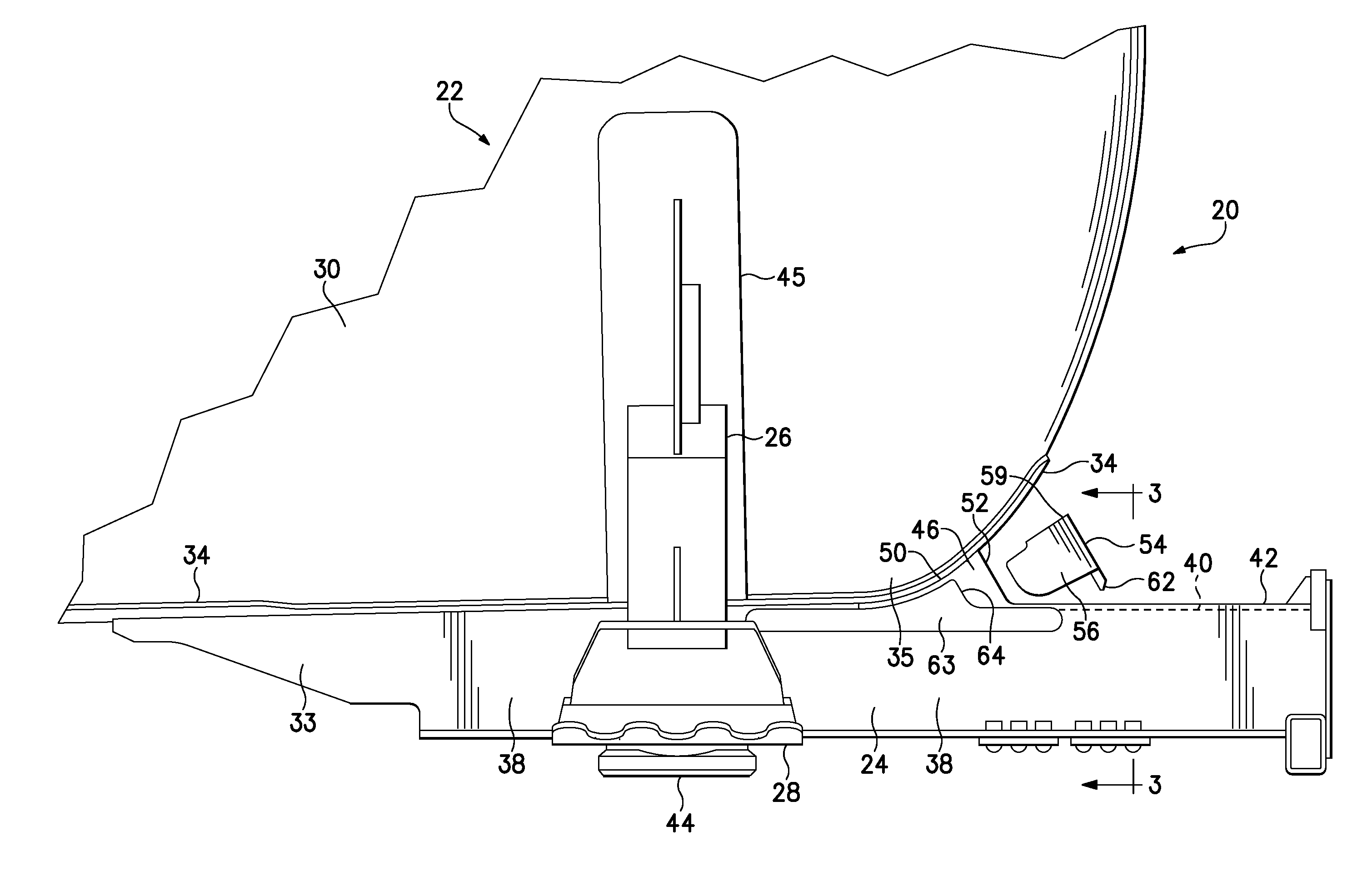
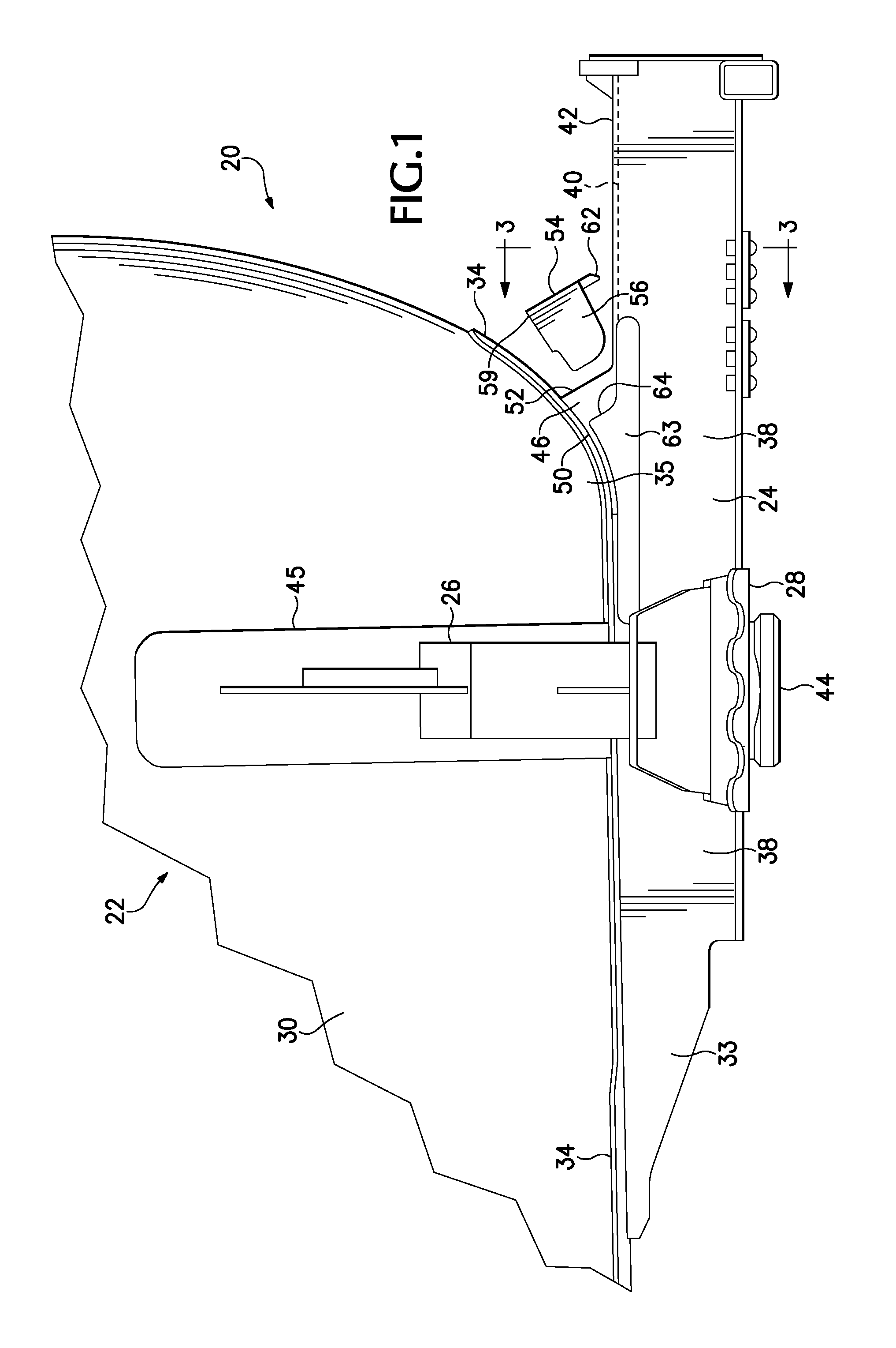
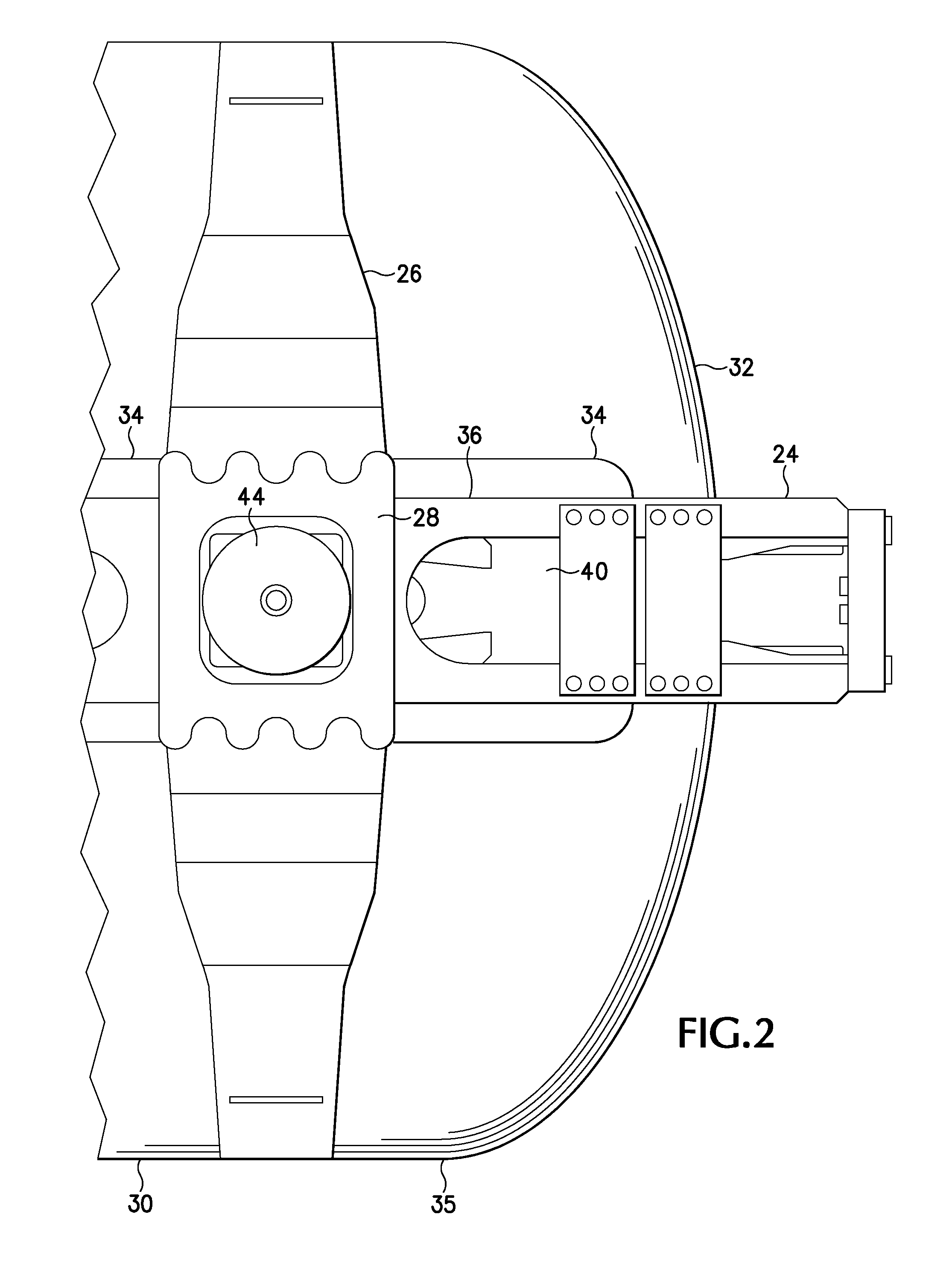
[0031]Referring now to the drawings which form a part of the disclosure herein, a portion of a railroad tank car 20 includes a tank 22 of steel or other suitable metal and intended for carrying liquid cargo, supported by a stub center sill 24 to which a tank saddle 26 is attached. Conventionally, the saddle 26 extends from a bolster 28 and around a generally cylindrical part 30 of the tank 22 a short distance longitudinally inboard from the convex head 32 of the tank 22. The stub center sill 24 may extend for distance inboard beyond the bolster 28 toward the center of the length of the car 20, as at 33.

[0032]As shown here, and in most cases, a doubler plate or head pad 34 of steel is present on a portion of the bottom of the tank above the stub center sill 24, extending around a transitional part 35 of the shape of the tank and onto the head 32, to receive and distribute into the tank 22 various forces applied to the center sill 24 during operation of a train including the car 20.

[0...


PUM


Abstract

A head brace and a method for attaching a stub sill to a tank of a railroad tank car by the use of such a head brace. A stub sill includes side plates having ears that extend upward to support the tank near where the head of the tank is attached, and a head brace is welded to the side plates and to the head of the tank in a weld joint that can be continuous along the head brace from the ears of the side plate to the center of the head brace. Doublers may be provided on the sill where the head brace is welded to the side plates.

Description

BACKGROUND OF THE INVENTION[0001]The present disclosure relates to railroad tank cars and in particular relates to attachment of stub sills to the ends of the tank of such a car.[0002]Railway tank cars may be used for carrying a variety of liquid, gaseous, and semi-liquid ladings. Such railway tank cars often include a horizontal, generally cylindrical tank. For many such tank cars, the tank not only carries the lading, but is also used as a primary structural member to carry longitudinal train loads.[0003]These cars typically have stub center sills on each end of the car along with transverse bolster assemblies. The sills carry couplers at their outer ends, and the bolsters have truck assemblies pivotally connected thereto to support the ends of the tank car on the railway tracks. Saddle assemblies, combined with the bolster assemblies, are typically provided at each end of the car. The saddle assembly usually is mated with a doubler plate or saddle pad that is attached to the tank...

Claims


Application Information

Patent Timeline
Patent Type & Authority Applications(United States)
IPC IPC(8): B61D5/06
CPCB61D5/06
Inventor SAXTON, GREGORY J.NIOSI, JOHN N.WOOLSTON, ROBERT D.
Owner GUNDERSON
Features
  • Generate Ideas
  • Intellectual Property
  • Life Sciences
  • Materials
  • Tech Scout
  • Unparalleled Data Quality
  • Higher Quality Content
  • 60% Fewer Hallucinations
Learn More