Control method of engine rapid warm-up system

a control method and engine technology, applied in the direction of machines/engines, mechanical equipment, transportation and packaging, etc., can solve the problems of not being able to avoid the reduction in the temperature of the cooling water in the heat accumulator, the cooling water gradually increases, and it still takes a certain time to reach the appropriate temperature, so as to accelerate the warm-up of the engine, improve fuel efficiency, and avoid the effect of reducing the temperature of the cooling water

Inactive Publication Date: 2009-10-01
CALSONIC KANSEI CORP
View PDF6 Cites 24 Cited by
  • Summary
  • Abstract
  • Description
  • Claims
  • Application Information

AI Technical Summary

Benefits of technology

[0009]In the control method of the engine rapid warm-up system, the control method is constructed so that the high temperature cooling water that is stored in the heat accumulator is sent to the engine to warm up the engine. Therefore, the high temperature cooling water can accelerate the warm-up of the engine, so that the engine can be surely started during the winter season and in cold regions.
[0010]In addition, the control method is construc...

Problems solved by technology

The technology disclosed in the patent application, however, cannot avoid reduction in the temperature of the cooling water in the heat accumulator over time because of the limit of capacity of the heat accumulator, although the hi...

Method used


Image

  • Control method of engine rapid warm-up system
  • Control method of engine rapid warm-up system
  • Control method of engine rapid warm-up system

Examples


first embodiment

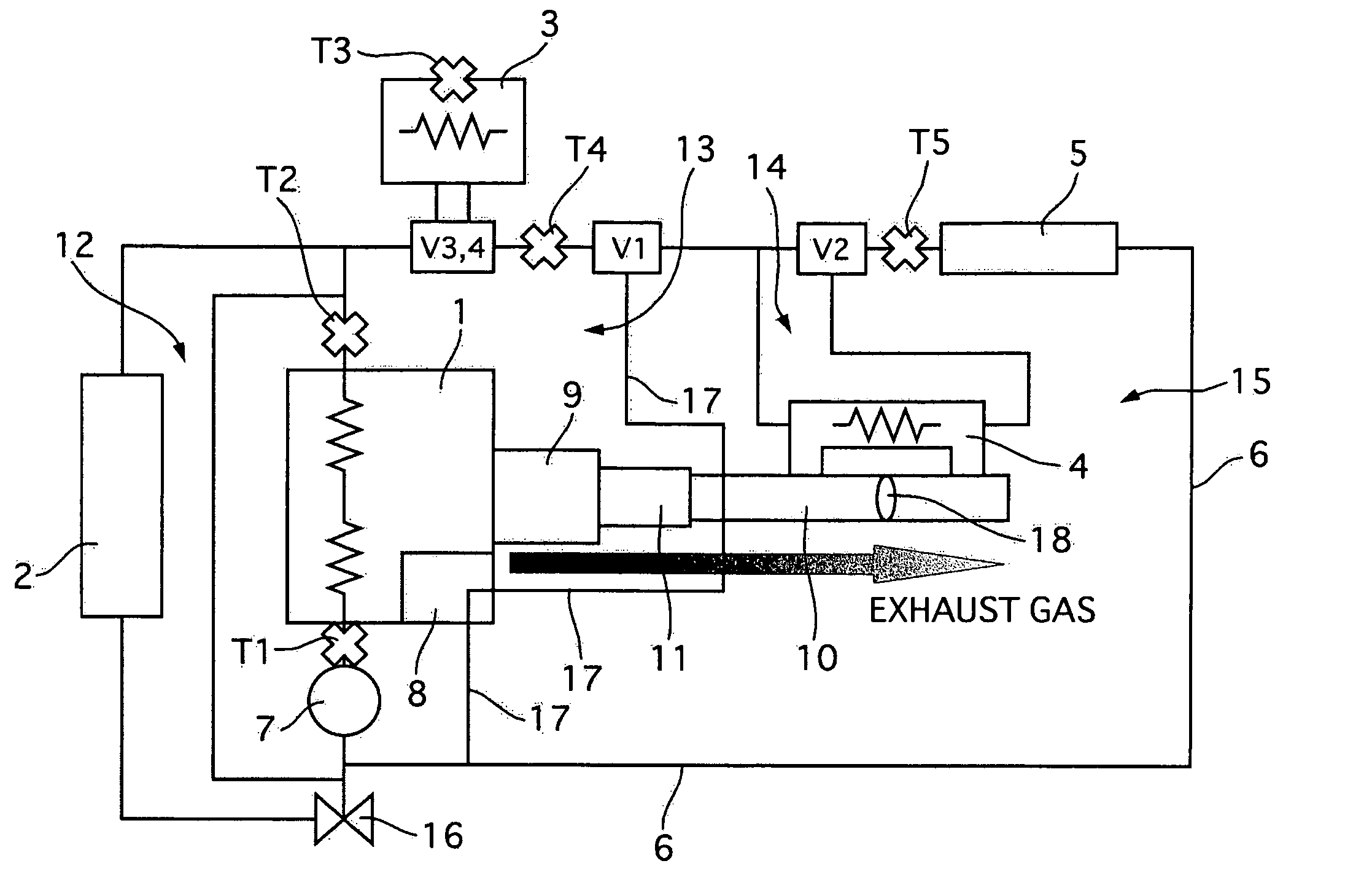
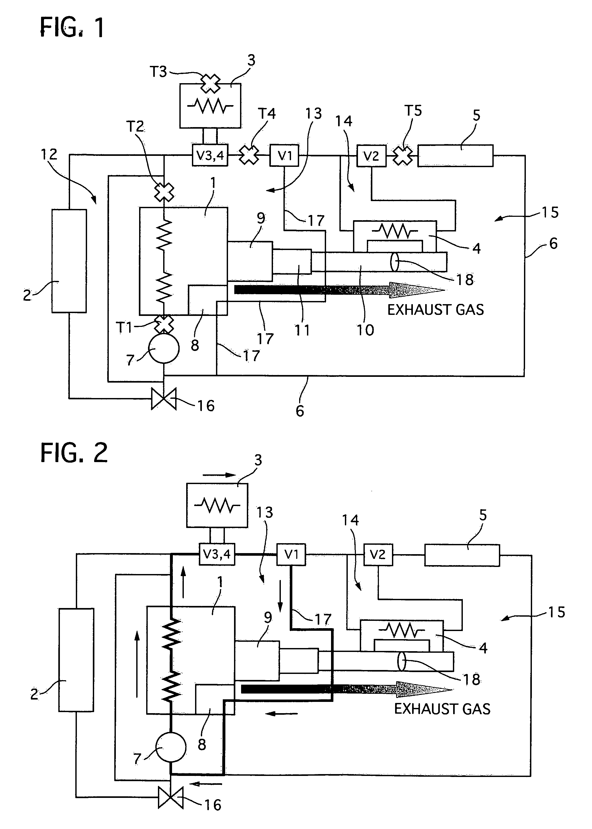
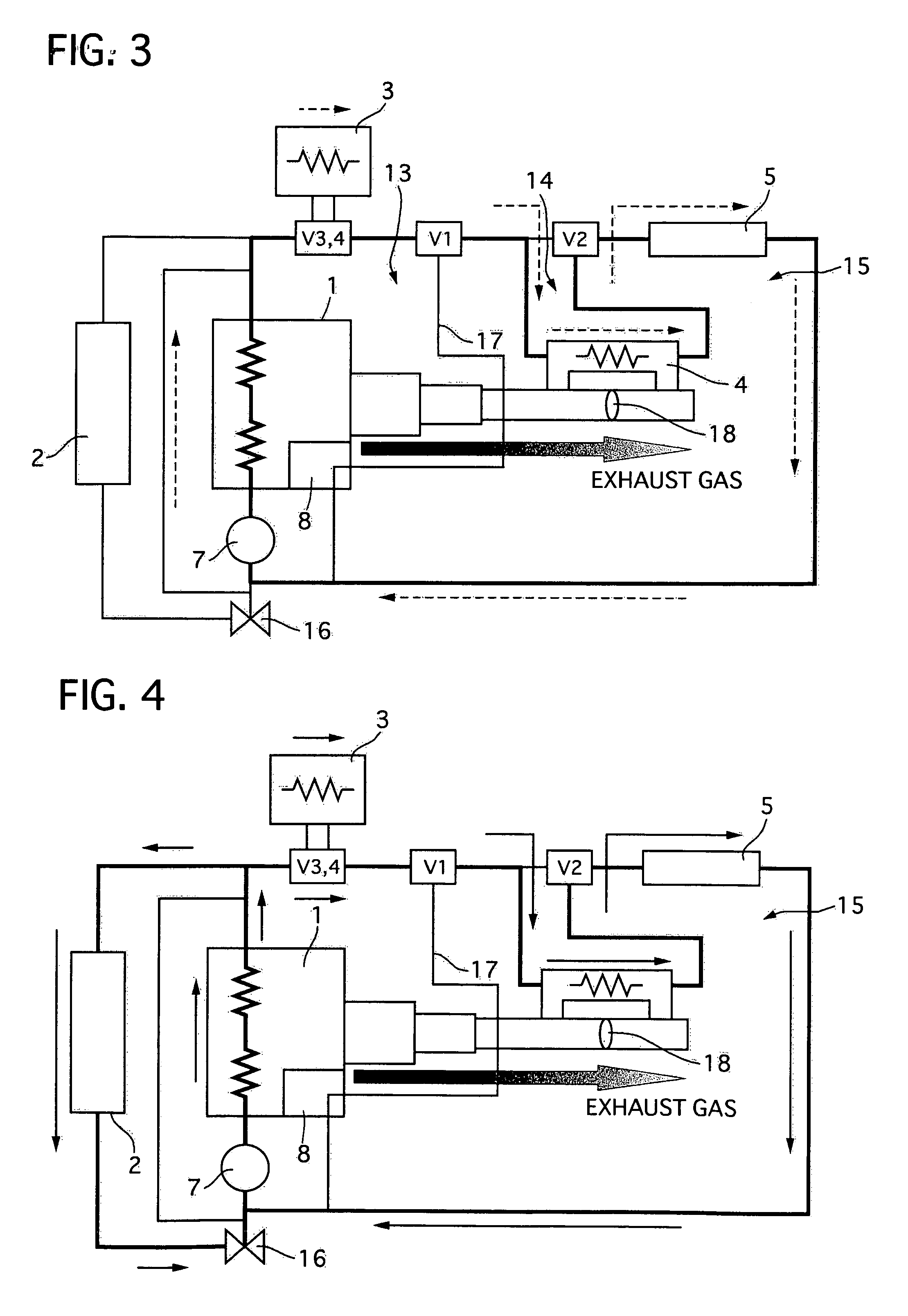
[0040]FIG. 1 is a schematic diagram illustrating an engine rapid warm-up system to which a control method of an embodiment according to the present invention is applied, FIG. 2 is a schematic diagram illustrating a flow direction of cooling water at engine start, FIG. 3 is a schematic diagram illustrating the flow direction of the cooling water immediately after the engine start, FIG. 4 is a schematic diagram illustrating the flow direction of the cooling water in a state where a heart recovery circuit is activated, FIG. 5 is a schematic diagram illustrating the flow direction of the cooling water when a motor vehicle is running, FIG. 6 is a schematic diagram illustrating the flow direction of the cooling water in a state where the heat recovery circuit is halted, FIG. 7 is a schematic diagram illustrating the engine rapid warm-up system in a state where the motor vehicle is stopped, and FIGS. 8A and 8B are a time chart illustrating an operation of the control method executed in the...


PUM


Abstract

An engine rapid warm-up system includes cooling water circulating through an engine 1, a radiator 2 introducing the cooling water to be cooled, a heat accumulator 3 storing the cooling water heated by the engine 1, and a pipe 6 and a water pump 7 that circulate the cooling water through the engine 1, the radiator 2 and the heat accumulator 3. In the system, high temperature cooling water that is stored in the heat accumulator 3 is controlled to be sent to and warm up the engine 1 at engine start, heat of exhaust gas is controlled to recover so that the cooling water obtained after heat recovery is circulated through and warms up the engine 1.

Description

TECHNICAL FIELD[0001]The present invention relates to a control method of an engine rapid warm-up system, and particularly it relates to a control method of an engine rapid warm-up system that effectively warms up an engine by utilizing high temperature cooling water stored in a heat accumulator and recovering heat of exhaust gas at engine start and circulate the cooling water through both of the heat accumulator and a radiator after engine warm-up.BACKGROUND OF THE INVENTION[0002]In general, in a water cooled engine of a motor vehicle, cooling water that is cooled down by a radiator is supplied to the water cooled engine through a cooling water supply passage, and the cooling water that is heated by the engine is returned through the cooling water return passage to the radiator, where the cooling water is cooled down due to heat transfer between the cooling water and the open air.[0003]In such a water cooled engine, there is a problem in that startability of the engine deteriorates...

Claims


Application Information

Patent Timeline
IPC IPC(8): F01P7/14
CPCB60H1/025F01N5/02F01N2240/02F01P7/165F01P2007/146F01P2060/16F01P2025/30F01P2025/32F01P2037/02F01P2060/08Y02T10/16F01P2011/205Y02T10/12
Inventor KIMURA, SATOSHIHORI, RYOICHINAKAJIMA, SHIROMATSUDAIRA, NORIMITSU
Owner CALSONIC KANSEI CORP
Why Eureka
Try Eureka