
Dead string completion assembly with injection system and methods

a technology of injection system and assembly, which is applied in the direction of drilling casings, drilling pipes, borehole/well accessories, etc., can solve the problems of increasing the inevitable liquid loading phenomenon, affecting the formation, and not being able to snub the well liv

Active Publication Date: 2009-10-01
BAKER HUGHES INC
View PDF9 Cites 68 Cited by
  • Summary
  • Abstract
  • Description
  • Claims
  • Application Information

AI Technical Summary

Benefits of technology

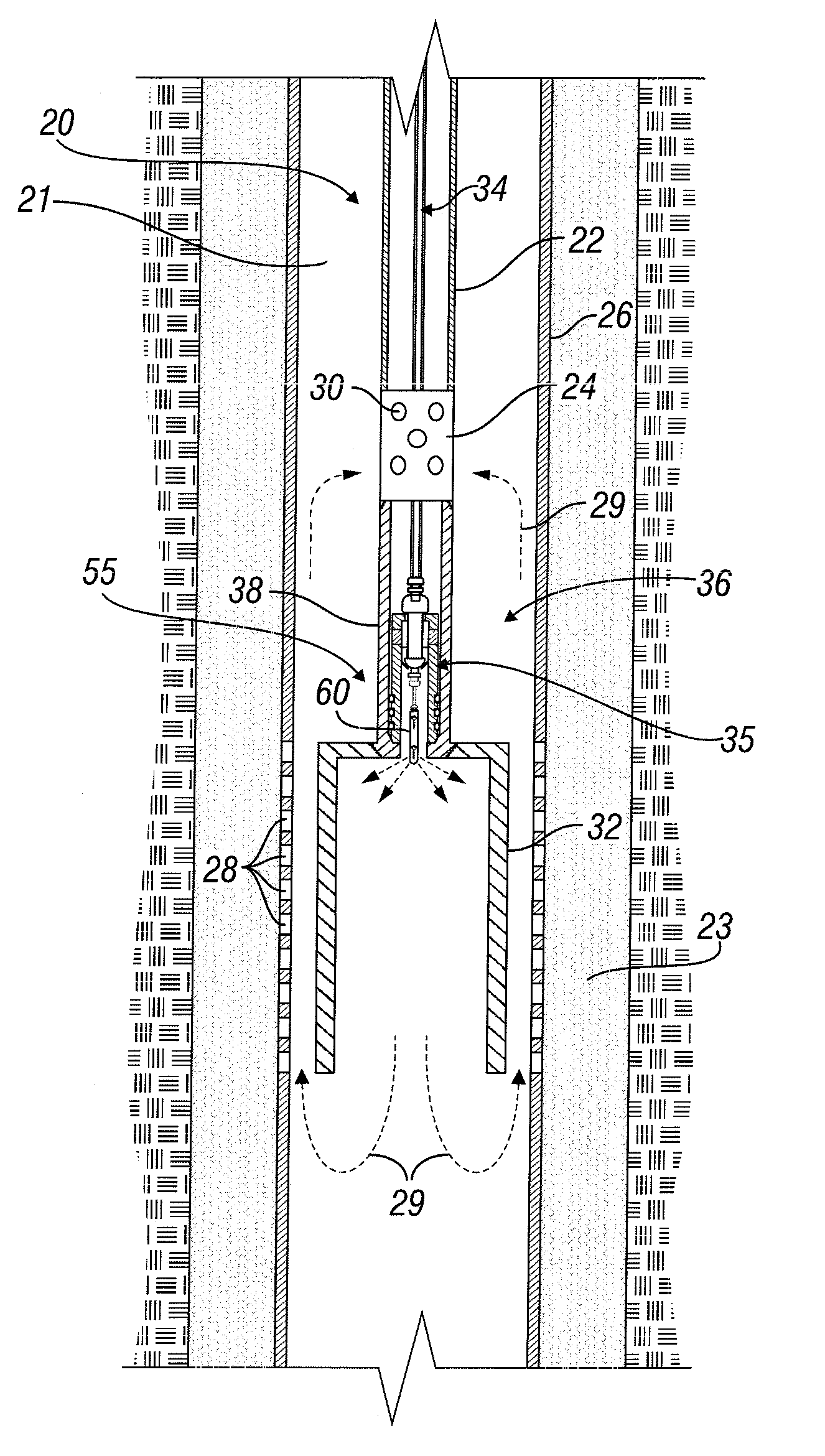
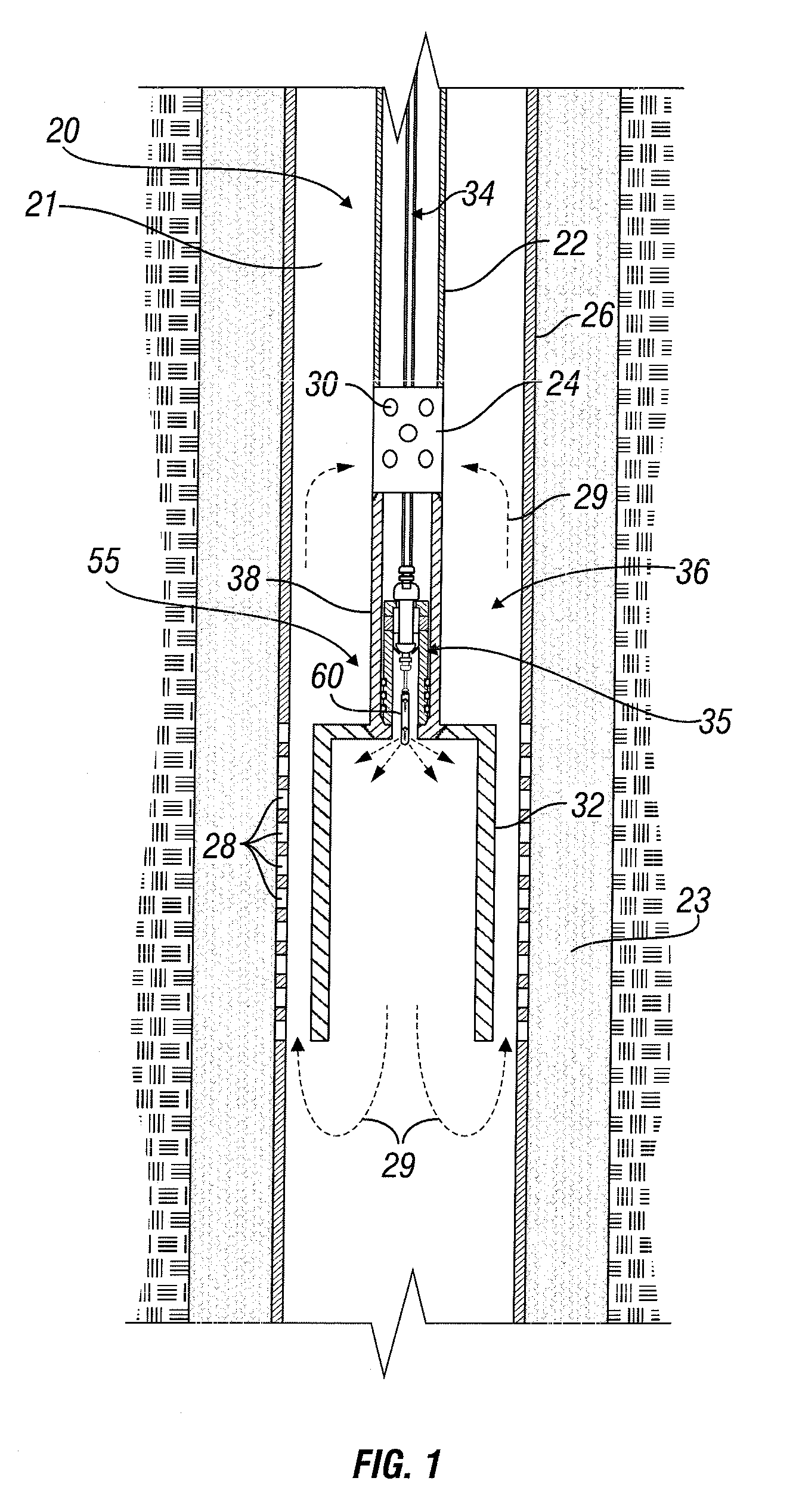
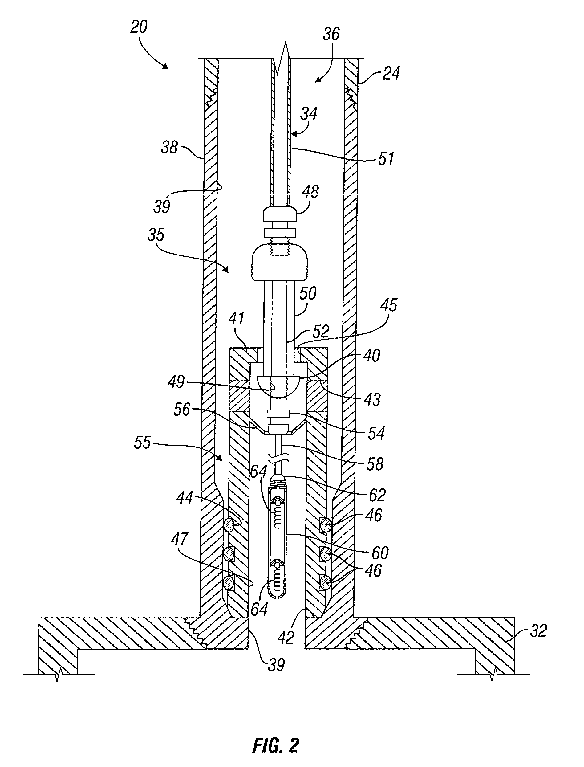
[0010]The injection system of these embodiments includes at least one delivery tubing and stopper. The delivery tubing has an outer diameter that is smaller than the inner diameters of the production tubing and dead string portion. The stopper is connected with the delivery tubing and configured to prevent fluid flow between the respective bores of the production tubing and dead string portion when the injection system is engaged with the hydrocarbon recovery system. The delivery tubing extends below the stopper and allows fluid to be ejected therefrom at a desired location within or below the dead string portion when the injection system is engaged with the hydrocarbon recovery system.
[0011]When the hydrocarbon recovery system is deployed in the well, the injection system of these embodiments may be engaged and disengaged with and removable from the hydrocarbon recovery system without removing the hydrocarbon recovery system from the well. Engagement of the injection system with the hydrocarbon recovery system fluidly isolates the production tubing and dead string portion, while disengagement thereof allows fluid communication between the respective bores of the production tubing and the dead string portion.
[0014]In these embodiments, an injection system is releasably engageable with the hydrocarbon recovery system and configured to be movable into and out of the well and the production tubing at least substantially independent of movement of the hydrocarbon recovery system. The injection system includes at least one delivery tubing having upper and lower ends and an outer diameter that is smaller than the inner diameter of the production tubing and dead string portion. The delivery tubing is capable of carrying at least one item of equipment proximate to its lower end. At least one stopper is connected with the delivery tubing and configured to prevent fluid flow between the respective bores of the production tubing and dead string portion when the injection system is engaged with the hydrocarbon recovery system. The delivery tubing extends a desired distance below the stopper and is capable of positioning the equipment carried thereby at a location within the dead string portion or below the dead string portion when the injection system is engaged with the hydrocarbon recovery system in the well. When the hydrocarbon recovery system is deployed in the well, the injection system may be engaged and disengaged with and removable from the hydrocarbon recovery system without removing the hydrocarbon recovery system from the well. Engagement of the injection system with the hydrocarbon recovery system fluidly isolates the production tubing from the dead string portion and disengagement of the injection system from the hydrocarbon recovery system allows fluid communication between the production tubing and the dead string portion.

Problems solved by technology

The larger diameter of the cased section adjacent to the perforations severely reduces the velocity of the production liquids exiting the perforations, which in turn may create liquid loading, a situation where the liquids settle at the bottom of the casing because the velocity is not sufficient enough to lift the fluids.
Often, extremely long perforated casing intervals, sometimes 3,000 feet or more, are exposed to longer sections of low velocities, again increasing the inevitable liquid loading phenomena.
For example, it may not be possible to snub the well live due to the capillary string and bands (i.e., strapping) on the outer diameter of the production tubing.
In such instance, in order to accommodate the strapping of the capillary tubing to the production tubing, the well must be killed and heavy hydrostatic fluids, which may cause damage to the formation, may need to be used.
For yet another potential example, in the case of backside capillary lines, the strapped capillary must penetrate the tubing hanger—which can be a costly endeavor.

Method used


Image

  • Dead string completion assembly with injection system and methods
  • Dead string completion assembly with injection system and methods
  • Dead string completion assembly with injection system and methods

Examples


Embodiment Construction

[0027]Characteristics and advantages of the present disclosure and additional features and benefits will be readily apparent to those skilled in the art upon consideration of the following detailed description of exemplary embodiments of the present disclosure and referring to the accompanying figures. It should be understood that the description herein and appended drawings, being of example embodiments, are not intended to limit the claims of this patent application, any patent granted hereon or any patent or patent application claiming priority hereto. On the contrary, the intention is to cover all modifications, equivalents and alternatives falling within the spirit and scope of the claims. Many changes may be made to the particular embodiments and details disclosed herein without departing from such spirit and scope.

[0028]In showing and describing preferred embodiments, like or identical reference numerals are used to identify common or similar elements. The figures are not nec...


PUM


Abstract

In some embodiments, apparatus useful for providing fluids or equipment into a subterranean well through a production tubing and associated dead string includes an injection system that is movable into and out of the well without removing the production tubing. The injection system includes a stopper that forms the seal that creates the dead string.

Description

[0001]This application claims priority to U.S. provisional patent application Ser. No. 61 / 039,245 filed Mar. 25, 2008, entitled “Deadstring Completion Assembly and Methods with Integral Injection System”, the disclosure of which is hereby incorporated by reference herein in its entirety.FIELD OF THE INVENTION[0002]The present disclosure relates generally to dead string completion technology and, more particularly, apparatus and methods relating to the injection of fluid or insertion of equipment into a subterranean well through a dead sting assembly.BACKGROUND OF THE INVENTION[0003]In typical hydrocarbon recovery completion systems, the production tubing is suspended in the casing and terminates above the top perforation. By terminating the production tubing above the top perforation, such as at 100 feet or more, the cased section of the well adjacent to the perforations has a larger diameter than the cased section adjacent to the production tubing. The larger diameter of the cased ...

Claims


Application Information

Patent Timeline
IPC IPC(8): E21B43/00E21B34/00E21B43/16E21B43/22
CPCE21B43/10E21B43/121E21B43/12
Inventor BOLDING, JEFFREY L.
Owner BAKER HUGHES INC
Learn More