
Skin for member with skin, member with skin and process for manufacturing the same

a skin and skin technology, applied in the field of skin for members with skin, can solve the problems of difficult and costly pulling out or separation of thus molded skin, less likely to be manufactured inexpensively, and difficult to assemble the skin, so as to reduce the man-hour requirement, improve decorativeness, and soft usability

Inactive Publication Date: 2009-10-01
TOYODA GOSEI CO LTD
View PDF0 Cites 0 Cited by
  • Summary
  • Abstract
  • Description
  • Claims
  • Application Information

AI Technical Summary

Benefits of technology

[0012]The present invention has been developed in view of such circumstances. It is therefore an object of the present invention to provide the following: a process for manufacturing member with skin, process which makes it possible to less expensively manufacture a member with skin that exhibits good decorativeness; a member with skin, member which is not only good in terms of decorativeness but also can be manufactured inexpensively; and a skin, which produces upgraded assemblage readiness in addition to exhibiting good decorativeness and being manufactured at reduced cost. In the following descriptions on the present invention, note that a part or section, which corresponds to the curled portion 121 in the conventional member with skin, will be hereinafter referred to as an “anchoring portion.”

Problems solved by technology

Consequently, in the course of manufacturing the conventional member with skin, it has been very troublesome to assemble the skin 102 with the substrate 101.
Accordingly, it would be difficult and costly to pull out or separate the thus molded skin 102 from a molding die 160 for skin.
Consequently, the molded skin 102 would be associated with such a problem that it is less likely to be manufactured inexpensively.
Consequently, there might arise such a problem that the parting line 128 has impaired the decorativeness of the thus manufactured member with skin.
As a result, not only the operation of assembling the skin 102 with the substrate 101 would be troublesome, but also would result in such a problem that a member with skin is likely to be manufactured expensively.

Method used


Image

  • Skin for member with skin, member with skin and process for manufacturing the same
  • Skin for member with skin, member with skin and process for manufacturing the same
  • Skin for member with skin, member with skin and process for manufacturing the same

Examples


examples

[0076]Hereinafter, manufacturing processes for member with skin according to the present invention will be described with reference to specific examples.

example no.1

Example No. 1

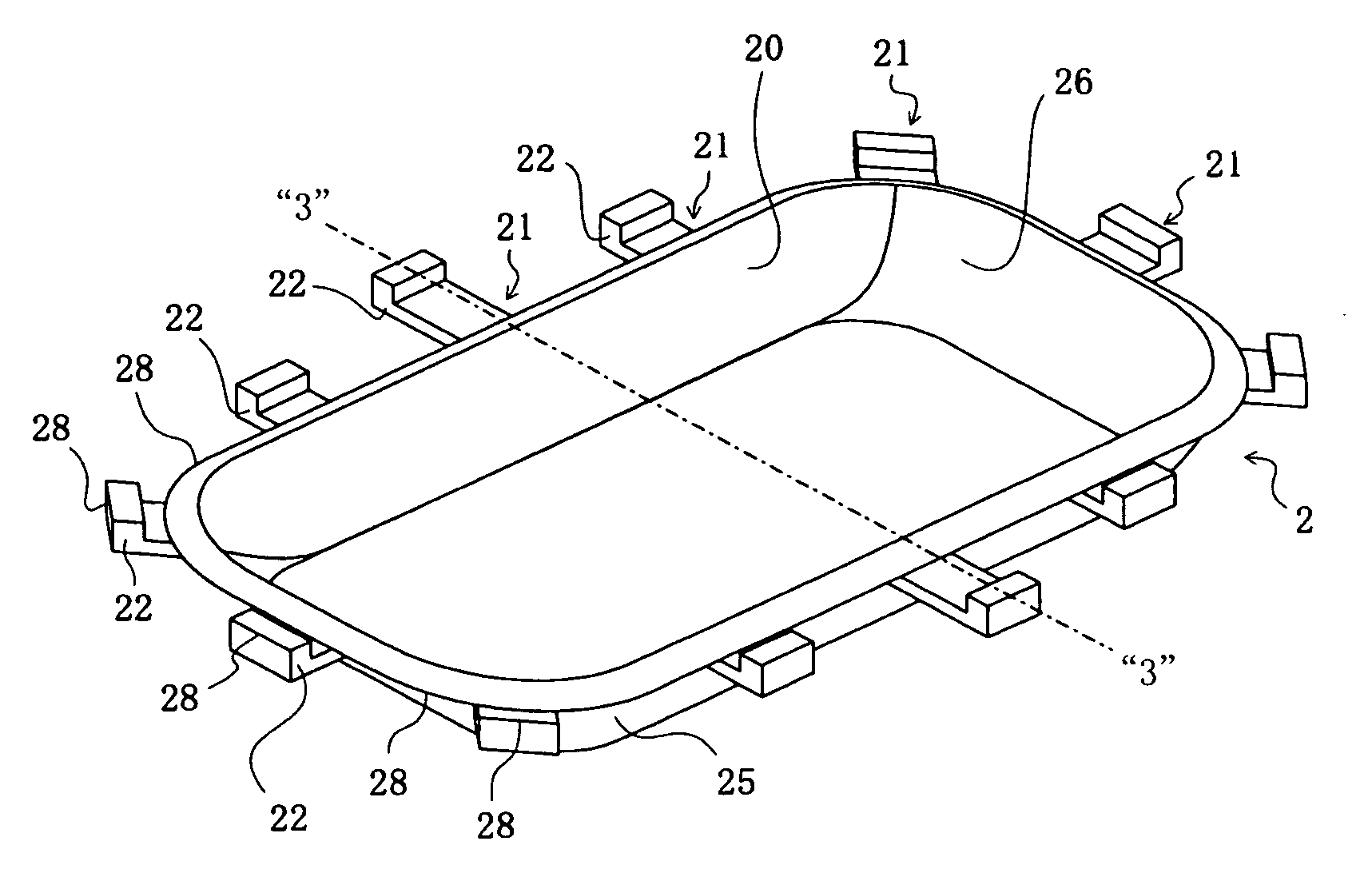
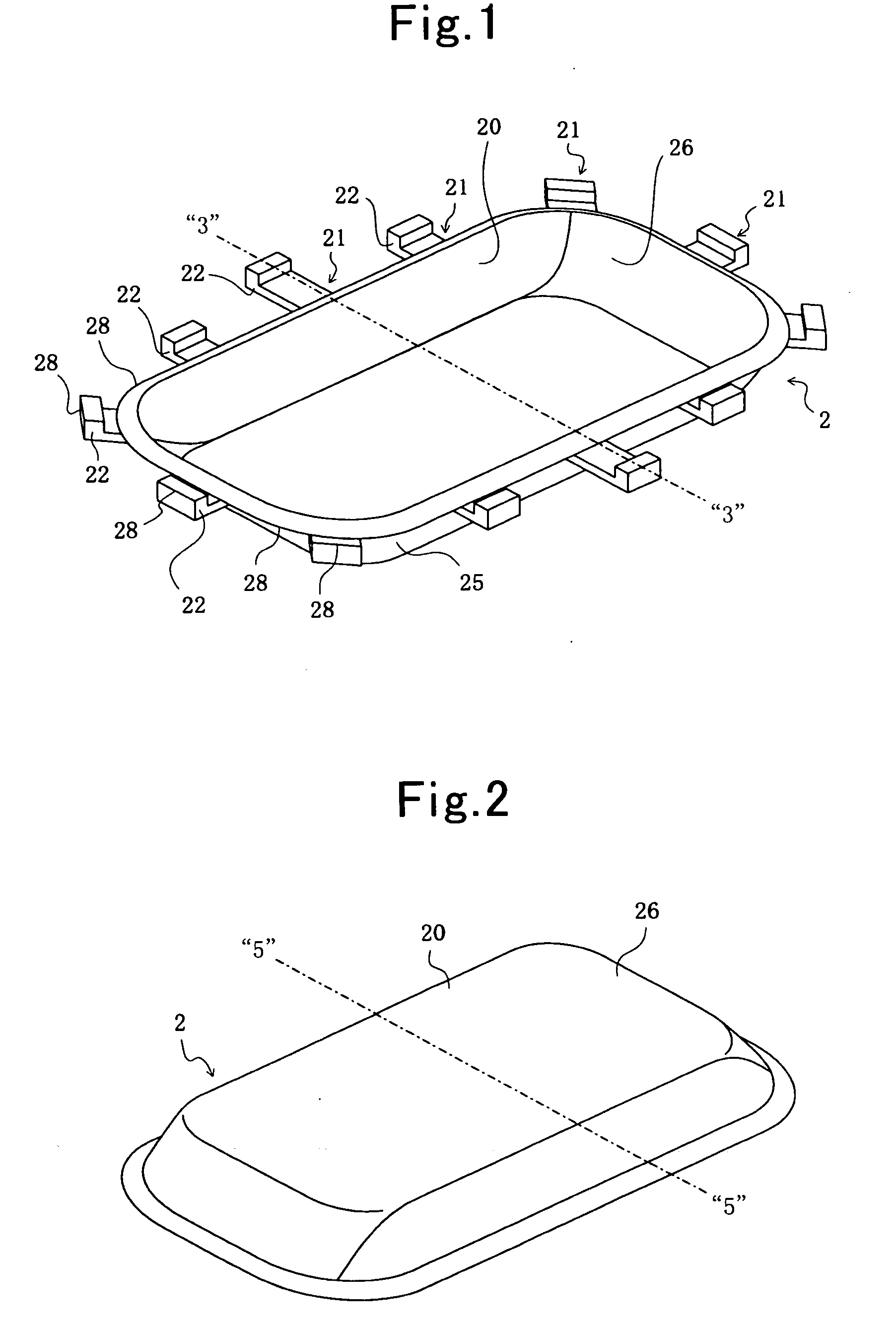
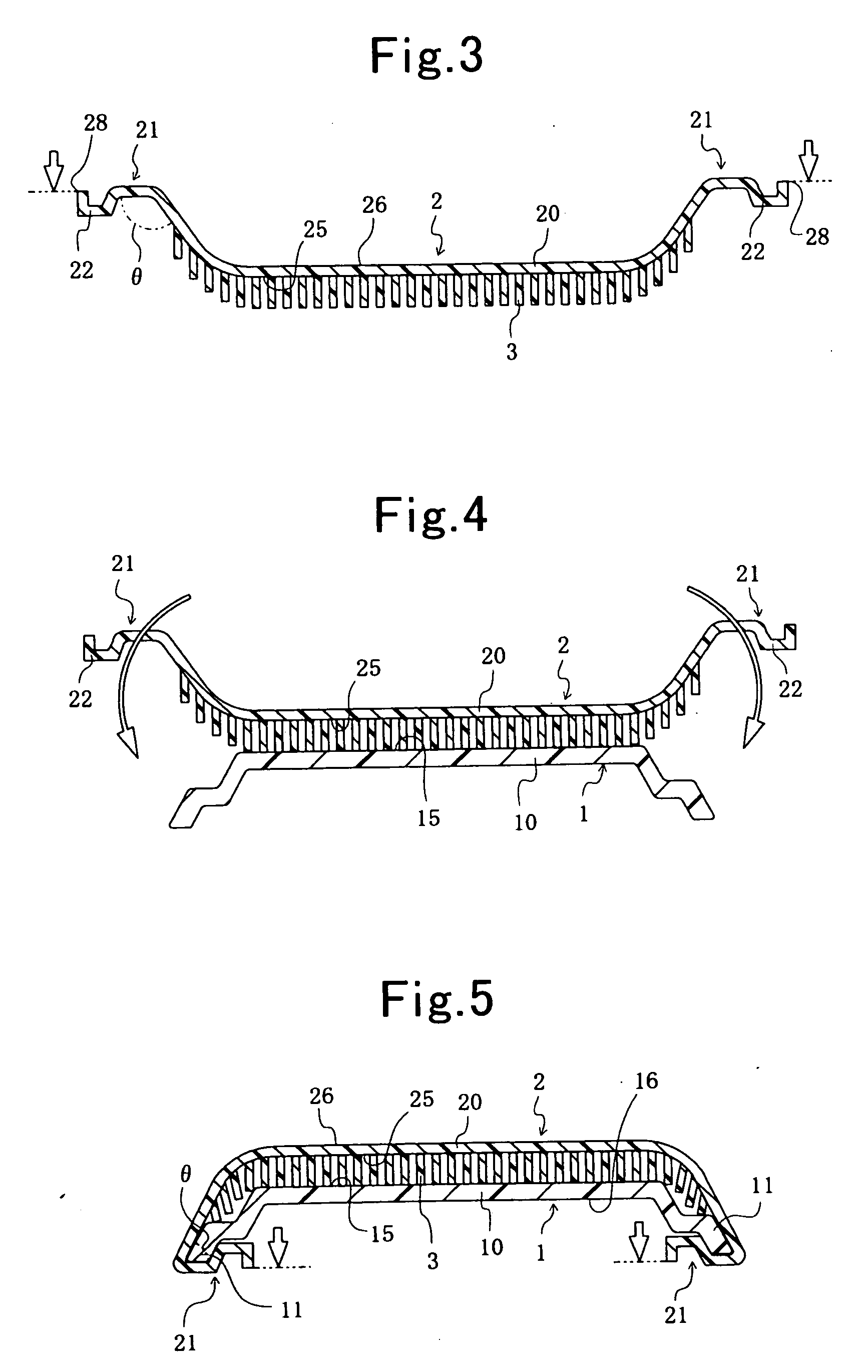
[0077]A process for manufacturing member with skin according to Example No. 1 of the present invention is provided with above-described optional features (1), (2), (4) and (5). Moreover, a member with skin according to Example No. 1 is directed to the present member with skin that is provided with above-described optional feature (1). In addition, a skin according to Example No. 1 is directed to the present skin that is provided with above-described optional feature (1). FIGS. 1 through 5 show explanatory diagrams for illustrating the process for manufacturing member with skin according to Example No. 1. Specifically, FIG. 1 is a perspective view for schematically illustrating a skin at a step of molding. FIG. 2 is a perspective view for schematically illustrating the skin at a step of assembling. FIG. 3 is a cross-sectional view for schematically illustrating how the skin shown in FIG. 1 appears when it is cut with the imaginary chain line “3”-“3” in FIG. 1. FIG. 4 is ...

example no.2

Example No. 2

[0093]A process for manufacturing member with skin according to Example No. 2 of the present invention is provided with above-described optional features (1) through (5). Moreover, a member with skin according to Example No. 2 is directed to the present member with skin that is provided with above-described optional feature (1). In addition, a skin according to Example No. 2 is directed to the present skin that is provided with above-described optional feature (1). FIGS. 6 and 7 show explanatory diagrams for illustrating the process for manufacturing member with skin according to Example No. 2. Specifically, FIG. 6 is a cross-sectional view for schematically illustrating how a skin appears when it is assembled with a substrate. FIG. 7 is a cross-sectional view for schematically illustrating a completed member with skin that is manufactured by the present process for manufacturing member with skin according to Example No. 2.

[0094]A member with skin according to Example N...


PUM

PropertyMeasurementUnit
degree of freedomaaaaaaaaaa
moldingaaaaaaaaaa
softaaaaaaaaaa

Abstract

A member with skin includes a substrate, and a skin. The skin includes a covering portion for covering the substrate on the front surface's side, and an anchoring portion for engaging with the substrate's rear-surface periphery. The skin has a covering surface being formed as a concaved planar shape, and an exposed surface being formed as a convexed planar shape. The anchoring portion is disposed successively to the covering portion's periphery, and extends inward toward the covering portion. The skin is made of soft material, and is molded independently of the substrate. Before being assembled with the substrate, the skin includes the covering portion whose covering surface is formed as a convexed planar shape, and whose exposed surface is formed as a concaved planar shape, and the anchoring portion is placed more outward than the covering portion's periphery lies.

Description

INCORPORATION BY REFERENCE[0001]The present invention is based on Japanese Patent Application No. 2008-83,903, filed on Mar. 27, 2008, the entire contents of which are incorporated herein by reference.BACKGROUND OF THE INVENTION[0002]1. Field of the Invention[0003]The present invention relates to a skin for member with skin, a member with skin, and a process for manufacturing the same. For example, a member with skin comprises a substrate, and a skin that has a covering portion and a curled portion. The skin's covering portion covers the substrate on a side of the substrate's front surface. The skin's curled portion engages with the substrate's rear-surface periphery.[0004]2. Description of the Related Art[0005]For example, Japanese Unexamined Patent Publication (KOKAI) Gazette No. 2004-129,744, and Japanese Unexamined Patent Publication (KOKAI) Gazette No. 2007-145,086 disclose a member with skin, respectively. A member with skin has been made by assembling a substrate and a skin t...

Claims


Application Information

Patent Timeline
Patent Type & Authority Applications(United States)
IPC IPC(8): B65D51/00B68G99/00
CPCB29C63/04Y10T29/486B29C66/71B29D99/0092B29K2023/00B29K2027/06B29K2075/00B29K2101/12B29C65/567B29C66/549B29C66/545B29C66/543B29C66/54B29C65/00B29C66/8322B29C66/1122B29K2055/02B29K2023/12
Inventor MIZOGUCHI, HIROKIKAKO, JUNICHIROSUZUKI, KOICHITAKAHASHI, EIICHI
Owner TOYODA GOSEI CO LTD
Learn More