
Resilient Vibration Isolator Having a Plurality of Bumps on an Engagement Surface Thereof

a technology of resilient isolators and bumps, which is applied in the direction of shock absorbers, machine supports, lighting and heating apparatus, etc., can solve the problems of reducing durability and high cost and investment, and affecting the performance of dual-rate resilient isolators

Active Publication Date: 2009-10-01
DENSO INTERNATIONAL AMERICA +1
View PDF18 Cites 40 Cited by
  • Summary
  • Abstract
  • Description
  • Claims
  • Application Information

AI Technical Summary

Benefits of technology

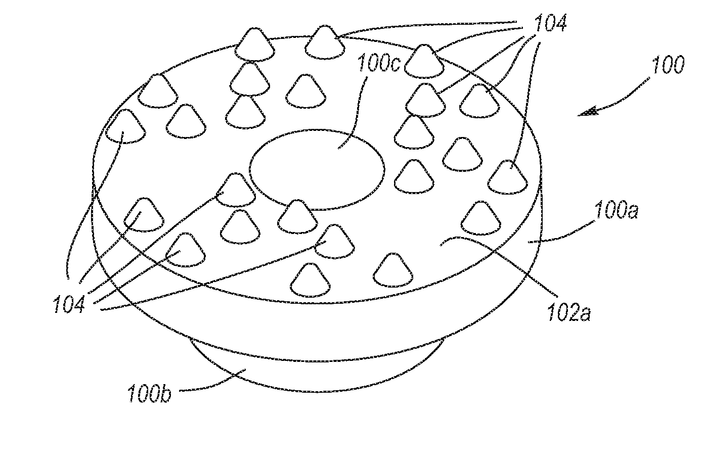
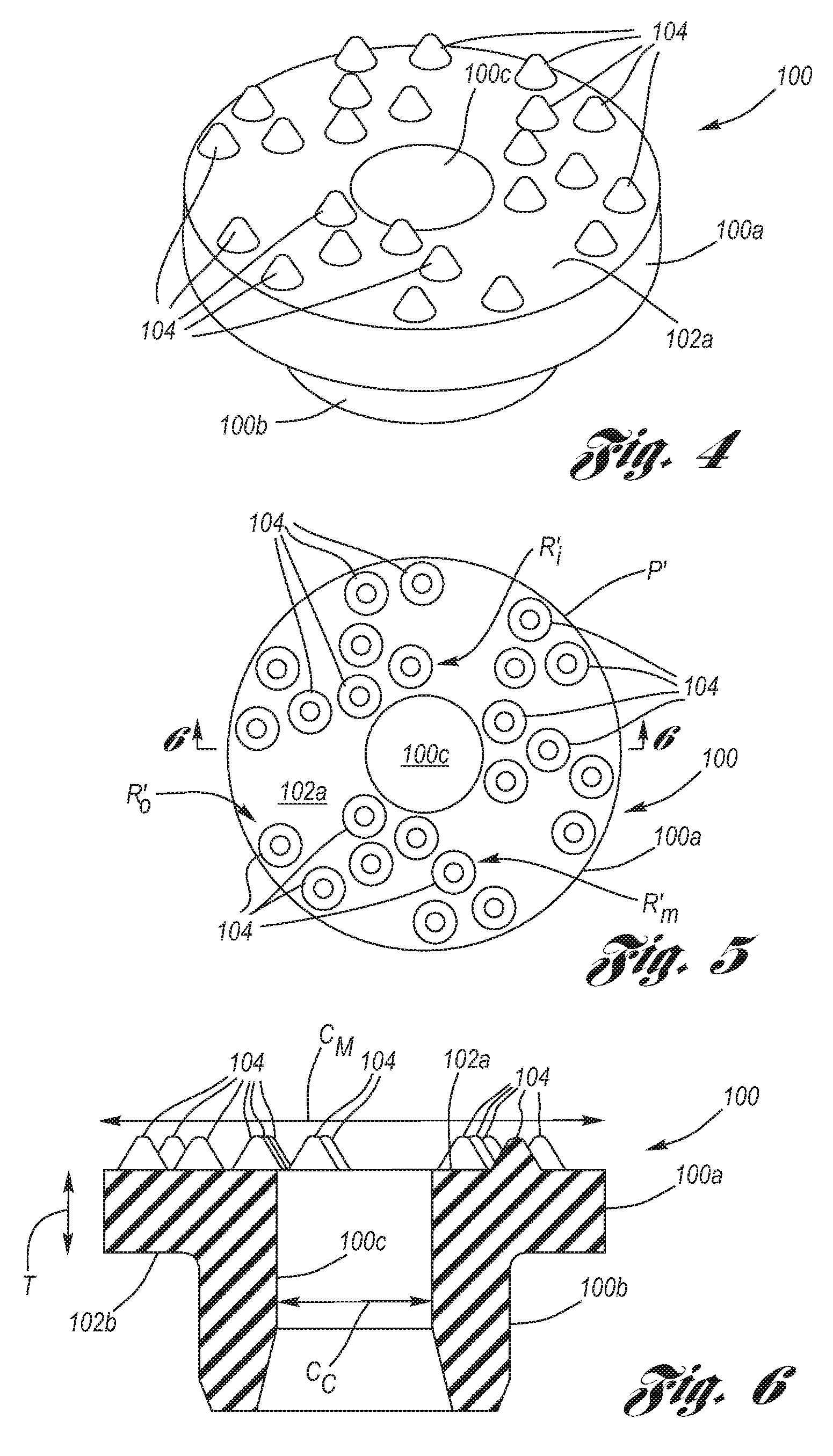
[0011]The present invention is a dual-rate resilient isolator having a plurality of raised, generally conical bumps formed in an engagement surface thereof, whereby the bumps in combination with the main body of the resilient isolator provide a dual-rate for isolating low amplitude CRFM vibration (via the relatively softer resiliency of the bumps) and isolating large amplitude road vibration (via the relatively hard resiliency of the main body) even though the bumps and the main body are composed of the same resilient material, the resilient isolator having low cost and investment, high durability, and excellent vehicle performance.
[0012]Each of the bumps is raised a preselected height in an axial direction above the engagement surface. It is preferred for each bump to be of a frustoconical shape characterized by either a flat apex or a bluntly rounded apex, the apex being located at the maximum height of the bump. The resilient isolator is composed of a resilient material of a preselected resiliency, wherein the bumps, due to their height and relative small conic area as compared to the thickness and relatively large area of the main body, provide a soft resiliency, even though the main body and the bumps are integral and composed of one in the same resilient material.
[0014]Accordingly, it is an object of the present invention to provide a dual-rate resilient isolator composed of a singular resiliency material, wherein a plurality of generally conical bumps formed in an engagement surface thereof in combination with a main body of the resilient isolator provide a dual-rate of resilient response to vibration over a range of amplitudes, wherein the resilient isolator has low cost and investment, high durability, and excellent vehicle performance.

Problems solved by technology

From a vehicle performance standpoint, dual-rate resilient isolators are superior to single rate resilient isolators; however, higher cost and investment, and reduced durability are detriments of the dual-rate resilient isolators.

Method used


Image

  • Resilient Vibration Isolator Having a Plurality of Bumps on an Engagement Surface Thereof
  • Resilient Vibration Isolator Having a Plurality of Bumps on an Engagement Surface Thereof
  • Resilient Vibration Isolator Having a Plurality of Bumps on an Engagement Surface Thereof

Examples


example

[0038]A subjective motor vehicle interior noise evaluation was performed using the General Motors' Uniform Test Scale (GMUTS), wherein:

No.PerformanceDisturbanceAnnoyancePereception by10ExcellentNoneNone, maskedNo one9ExcellentNoneJust detectableTrained observer8GoodTraceSlightCritical observer7GoodTraceMildCritical observer6FairLightModerateCritical observer5FairLightComplaintAverage observer4PoorAnnoyingObjectionableAll observers3PoorAnnoyingStrong objectionAll observers2BadSevereRedress requiredAll observers

[0039]Various resilient isolators were tested and evaluated according to the GMUTS, comparing a non-shear type prior art resilient isolator, a shear-style prior art resilient isolator, and various forms of the dual-rate resilient isolator according to the present invention as per FIGS. 5 and 8, as indicated by the below table:

TABLEIsolatorSteering Wheel VibrationInterior NoiseEvaluationA5.0-5.55.0unacceptableB5.56.0unacceptableC6.06.0-6.5unacceptableD6.56.5marginalE6.56.5-7.0ma...


PUM

PropertyMeasurementUnit
heightaaaaaaaaaa
heightaaaaaaaaaa
heightaaaaaaaaaa

Abstract

A dual-rate resilient isolator having a plurality of raised, generally conical bumps formed on an engagement surface thereof. The bumps in combination with a main body of the resilient isolator provide a dual-rate for isolating CRFM noise vibration and or other vibrations (via the relatively softer resiliency of the bumps) and isolating road vibration and shock (via the relatively harder resiliency of the main body) even though the bumps and the main body are composed of the same resilient material.

Description

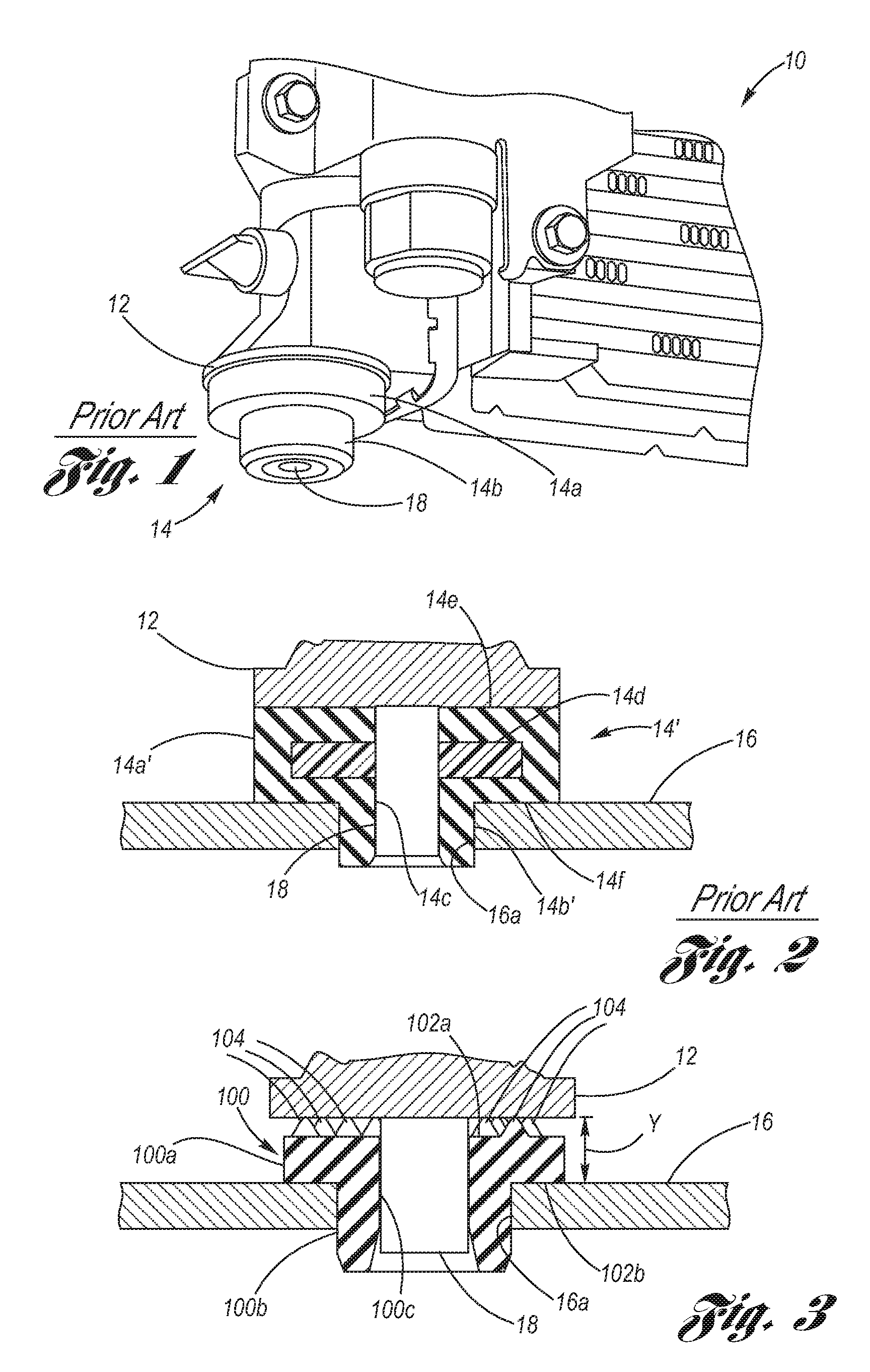
TECHNICAL FIELD[0001]The present invention relates to resilient vibration isolators, particularly those used for isolating vibration of motor vehicle condenser, radiator and fan modules (CRFM), and more particularly to a resilient vibration isolator having opposed engagement surfaces, wherein an engagement surface thereof is provided with a plurality of raised bumps.BACKGROUND OF THE INVENTION[0002]In situations where joined articles are subject to vibration, it may be desirable to isolate the vibration from passing from any one of the articles to the other. An example of such a situation occurs in motor vehicles with respect to the mounting of a condenser, radiator fan module (commonly referred to in the art as a “CRFM”).[0003]As shown by way of example at FIGS. 1 and 2, a CRFM 10 includes a mounting foot 12 one at each side thereof (only one side being shown in FIG. 1), wherein the mounting foot rests upon a resilient isolator 14, which in turn rests upon a cradle 16 (see FIG. 2)....

Claims


Application Information

Patent Timeline
Patent Type & Authority Applications(United States)
IPC IPC(8): F16F15/00
CPCF16F1/376F16F1/3732
Inventor TING, KENTLEWITZKE, CRAIG W.FIX III, PATRICK E.TAYLOR, DWAYNE R.
Owner DENSO INTERNATIONAL AMERICA
Learn More