
Power tool carriers

a tool carrier and tool technology, applied in the field of power tool carriers, can solve the problems of reducing the service life of the tool carrier, the tool bits can be easily dropped out of the tool bit holding sleeves, and the inability of rubber bands to sufficiently and uniformly fasten the tool bits, so as to reduce the number of tool bits

Inactive Publication Date: 2009-10-01
MAKITA CORP
View PDF21 Cites 8 Cited by
  • Summary
  • Abstract
  • Description
  • Claims
  • Application Information

AI Technical Summary

Benefits of technology

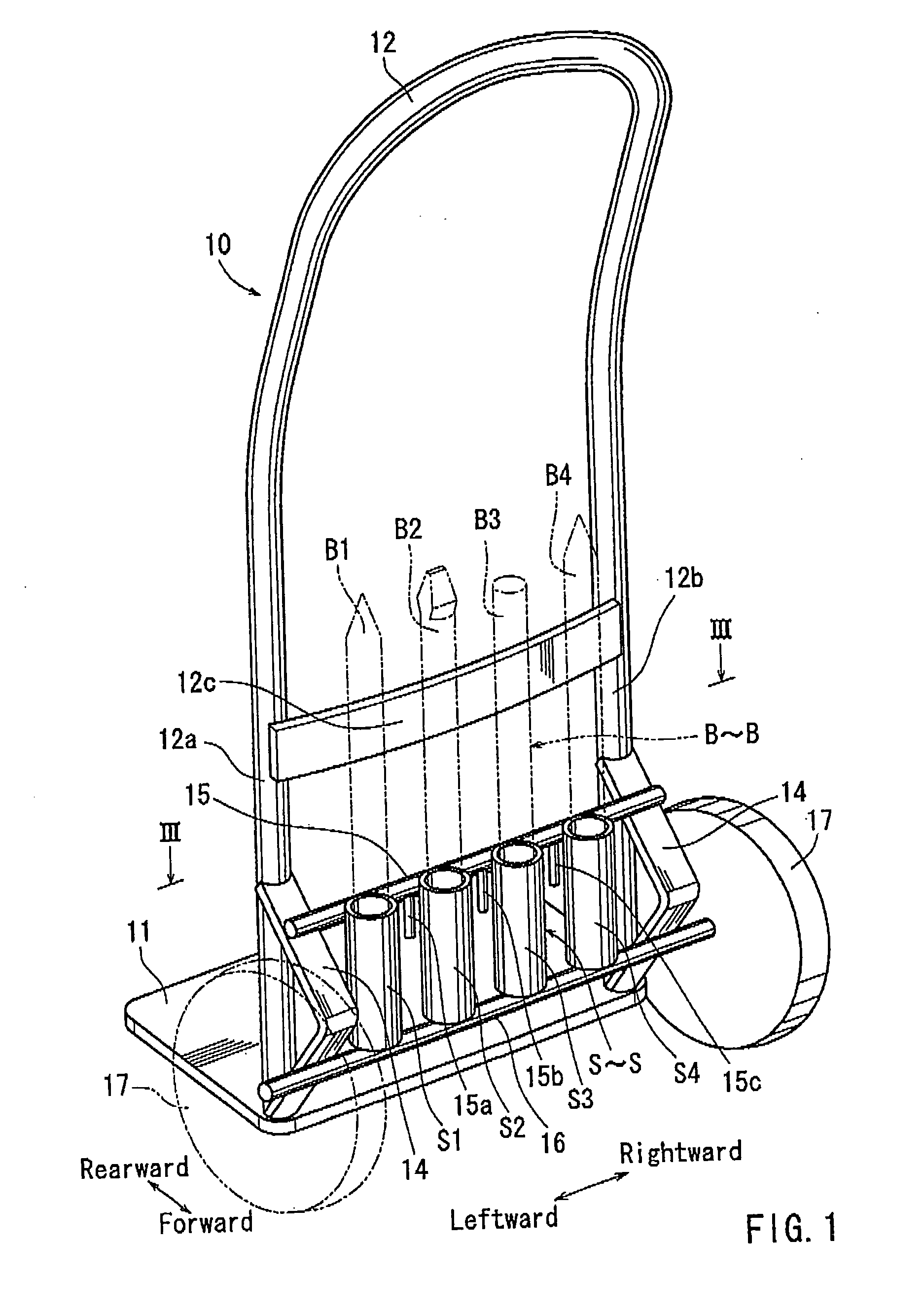
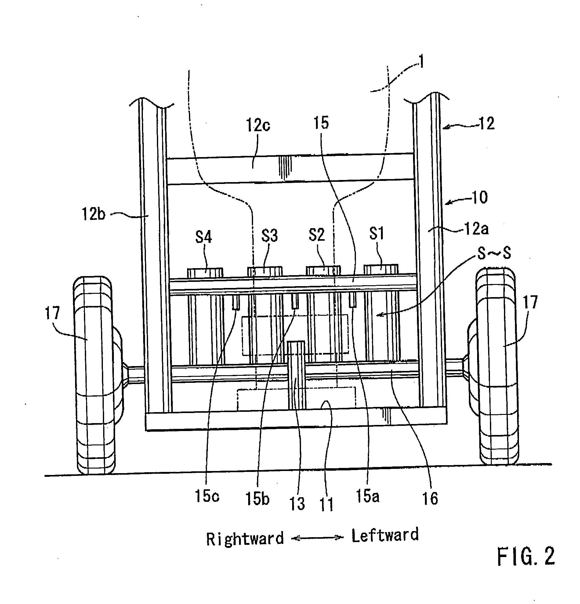
[0011]In one aspect of the present invention, a carrier for carrying a power tool may include a tool bit holder supporting at least one tool bit and a tool bit restraint device that is capable of preventing the at least one tool bit from being dropped out of the tool bit holder. The tool bit restraint device includes a tool bit restraint member. The tool bit restraint member is arranged and constructed so as to substantially uniformly press the at least one tool bit, thereby restrain g the at least one tool bit.
[0012]According to this aspect, the at least one tool bit can be reliably restrained by the tool bit restraint member. Therefore, the at least one tool bit can be effectively prevented from being dropped out of the tool bit holder even when the carrier is in a lying position.
[0013]Optionally, the tool bit restraint member can be arranged and constructed so as to cover the at least one tool bit. In this structure, the at least one tool bit can be similarly reliably restrained by the tool bit restraint member, so as to be effectively prevented from being dropped out of the tool bit holder.

Problems solved by technology

Generally, it is difficult to carry a relatively large power tool in hand.
In particular, when the power tool carrier is loaded into the vehicle while maintained in the lying position in order to transport the power tool by the vehicle, the tool bits can be easily dropped out of the bit holding sleeves by vibration or sudden movement of the vehicle.
Conventionally, in order to avoid the tool bits from being dropped out of the bit holding sleeves, the tool bits are simply elastically clamped by rubber bands, However, such rubber bands cannot sufficiently and uniformly fasten the tool bits.
As a result, the rubber bands cannot reliably prevent the tool bits from being dropped out of the bit holding sleeves of the tool bit holder.

Method used


Image

  • Power tool carriers
  • Power tool carriers
  • Power tool carriers

Examples


first embodiment

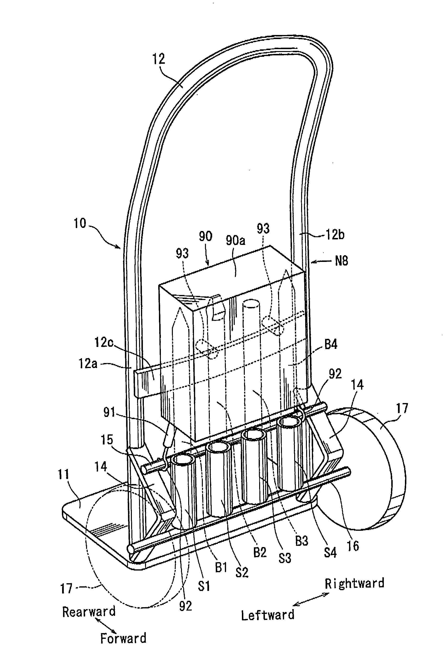
[0056]In this embodiment, the carrier 10 has a tool bit restraint device N3 in place of the tool bit restraint device N1 of the Unlike the tool bit restraint device N1, the tool bit restraint device N3 may preferably include a belt-shaped leaf spring or spring band 40 (the tool bit restraint member) in place of the rubber band 20 of the tool bit restraint device N1. However, the tool bit restraint device N3 does not include engagement projections corresponding to the engagement projections 15a-15c (the engagement member) of the rubber band 20 of the tool bit restraint device N1. Similar to the rubber band 20 of the tool bit restraint device N1, the spring band 40 has a pair of hooks 40a and 40b formed in both ends thereof. Further, the spring band 40 does not have an engagement hole corresponding to the engagement hole 20c of the rubber band 20 of the tool bit restraint device N1.

[0057]As will be apparent from FIG. 7, four C-shaped retainer recesses 40c are formed in the spring ban...

third embodiment

[0063]In this embodiment, the carrier 10 has a tool bit restraint device N4 in place of the tool bit restraint device N3 of the Similar to the tool bit restraint device N3, the tool bit restraint device N4 may preferably include a spring band 50 (the tool bit restraint member). However, unlike the tool bit restraint device N3, the spring band 50 has a support portion 50a formed in one end thereof and a hook 50b formed in the other end thereof. The support portion 50a of the spring band 50 is horizontally rotatably connected to the leg portion 12a of the handle 12. Conversely, the hook 50b of the spring band 50 is constructed to engage the leg portion 12b of the handle 12.

[0064]Further, unlike the tool bit restraint device N3, four retainer projections 50c are formed in the spring band 50, so as to be respectively projected rearwardly. The retainer projection 50c may preferably be formed at intervals that substantially correspond to the intervals of the bit holding sleeves S (the to...

fourth embodiment

[0098]In this embodiment, the carrier 10 has a tool bit restraint device N9 in place of the tool bit restraint device N4 of the However, unlike the tool bit restraint device N4, the tool bit restraint device N9 may preferably include a restraint frame 100 (the tool bit restraint member). The restraint frame 100 is rotatably connected to the brackets 14 via support sleeves 105 and 106, so as to be rotatable vertically (forwardly and rearwardly) between a rotational position (a fastening position) shown by solid lines in FIG. 13 and a rotational position (a release position) shown by broken lines in FIG. 13.

[0099]As shown in FIG. 14, four hemicircle-shaped retainer recesses 101-104 are formed in the restraint frame 100. Each of the retainer recesses 101-104 is opened rearwardly and has the substantially same diameter as the diameter of each of the tool bits B. Further, the retainer recesses 40c may preferably be formed at the substantially same intervals as the bit holding sleeves S ...


PUM


Abstract

A carrier for carrying a power tool may include a tool bit holder supporting at least one tool bit and a tool bit restraint device that is capable of preventing the at least one tool bit from being dropped out of the tool bit holder. The tool bit restraint device includes a tool bit restraint member. The tool bit restraint member is arranged and constructed so as to substantially uniformly press the at least one tool bit, thereby restraining the at least one tool bit.

Description

[0001]This application claims priority to Japanese patent application serial number 2008-086813, the contents of which are incorporated herein by reference.BACKGROUND OF THE INVENTION[0002]1. Field of the Invention[0003]The present invention relates to power tool carriers. More particularly, the present invention relates to power tool carriers generally called hammer carts that are capable of carrying power tools (e.g., power hammers and power breakers) and tool bits (e.g., hammer bits and breaker bits) that are attached to the power tools. Further, the hammer bits and the breaker bits will be simply referred to as bits.[0004]2. Description of Related Art[0005]Generally, it is difficult to carry a relatively large power tool in hand. Examples of such a power tool are a power hammer and a power breaker that are used to chip a concrete product or to crush a concrete block. Therefore, in order to carry the power tool, a power tool carrier (a hammer cart) having wheels is used. Further,...

Claims


Application Information

Patent Timeline
IPC IPC(8): B62B1/14
CPCB62B1/262B62B1/14
Inventor ARAKAWA, TAKUOTATEYAMA, SHINSUKESUMI, TAKUYAMIWA, MASAOKAKIUCHI, YASUHIRO
Owner MAKITA CORP
Learn More