Method and apparatus for measuring AC voltages

a technology of ac voltage and measurement method, applied in the direction of voltage/current isolation, fault location, instruments, etc., can solve the problems of transformers continuously consuming power, distortion problems, and bulky transformers,

Active Publication Date: 2009-10-01
ENPHASE ENERGY
View PDF0 Cites 34 Cited by
  • Summary
  • Abstract
  • Description
  • Claims
  • Application Information

AI Technical Summary

Problems solved by technology

Such transformers are bulky, heavy, and expensive.
Additionally, these transformers continuously consume power and may exhibit distortion problems.

Method used


Image

  • Method and apparatus for measuring AC voltages
  • Method and apparatus for measuring AC voltages
  • Method and apparatus for measuring AC voltages

Examples


Embodiment Construction

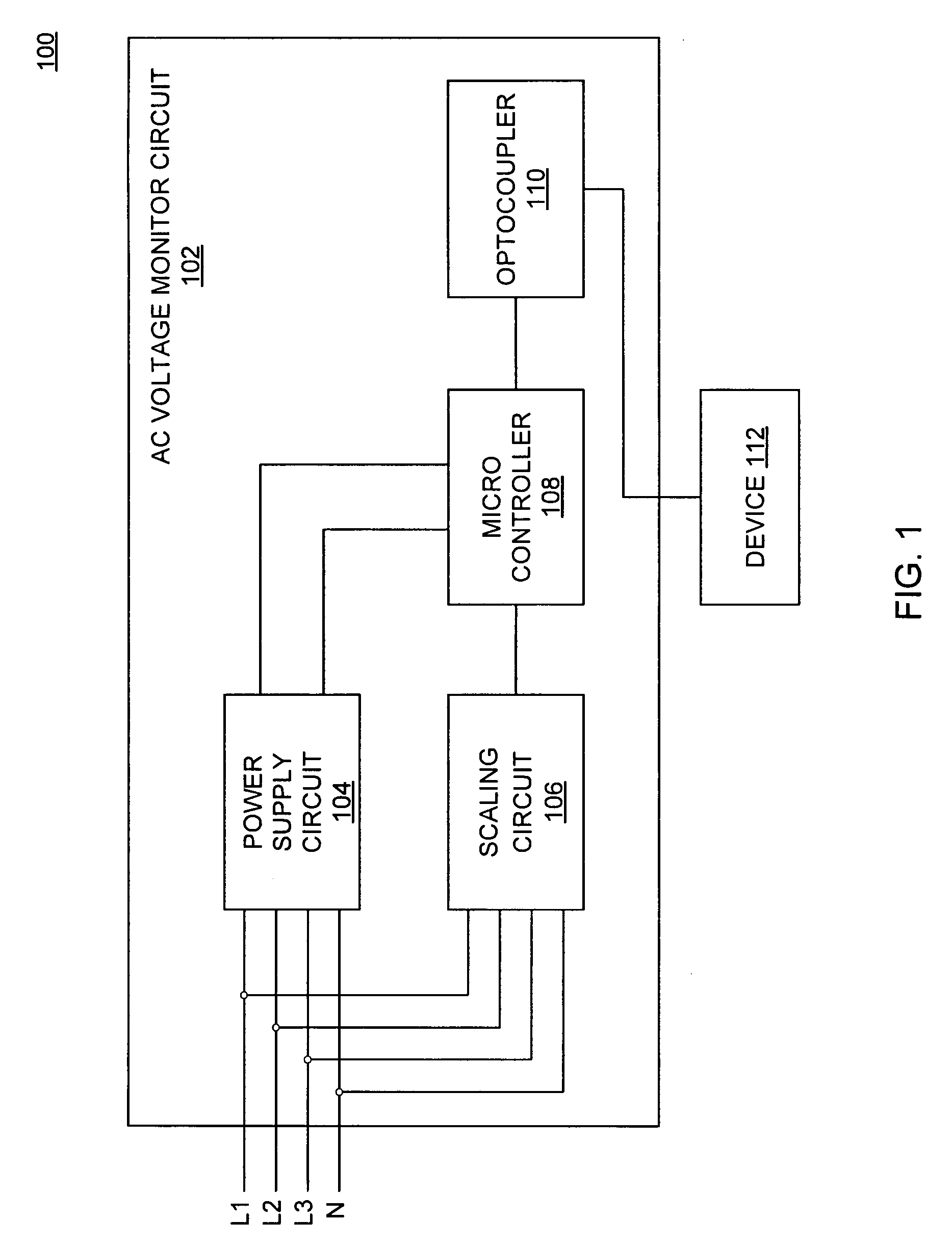
[0015]FIG. 1 is a block diagram of an AC voltage monitor 102 for providing isolated AC voltage monitoring in accordance with one or more embodiments of the present invention. The AC voltage monitor 102 is coupled to a three-phase AC commercial power grid (“grid”) and to a device 112, and comprises a power supply circuit 104, a scaling circuit 106, a microcontroller 108, and an optocoupler 110 (i.e., a solid state isolation device). In some embodiments, the power supply circuit 104 may be a state of the art AC / DC converter (e.g., a diode bridge, capacitor and flyback converter). The device 112 may be any device requiring voltage measurements from an AC line, such as a UPS, inverter, micro-inverter, and the like.

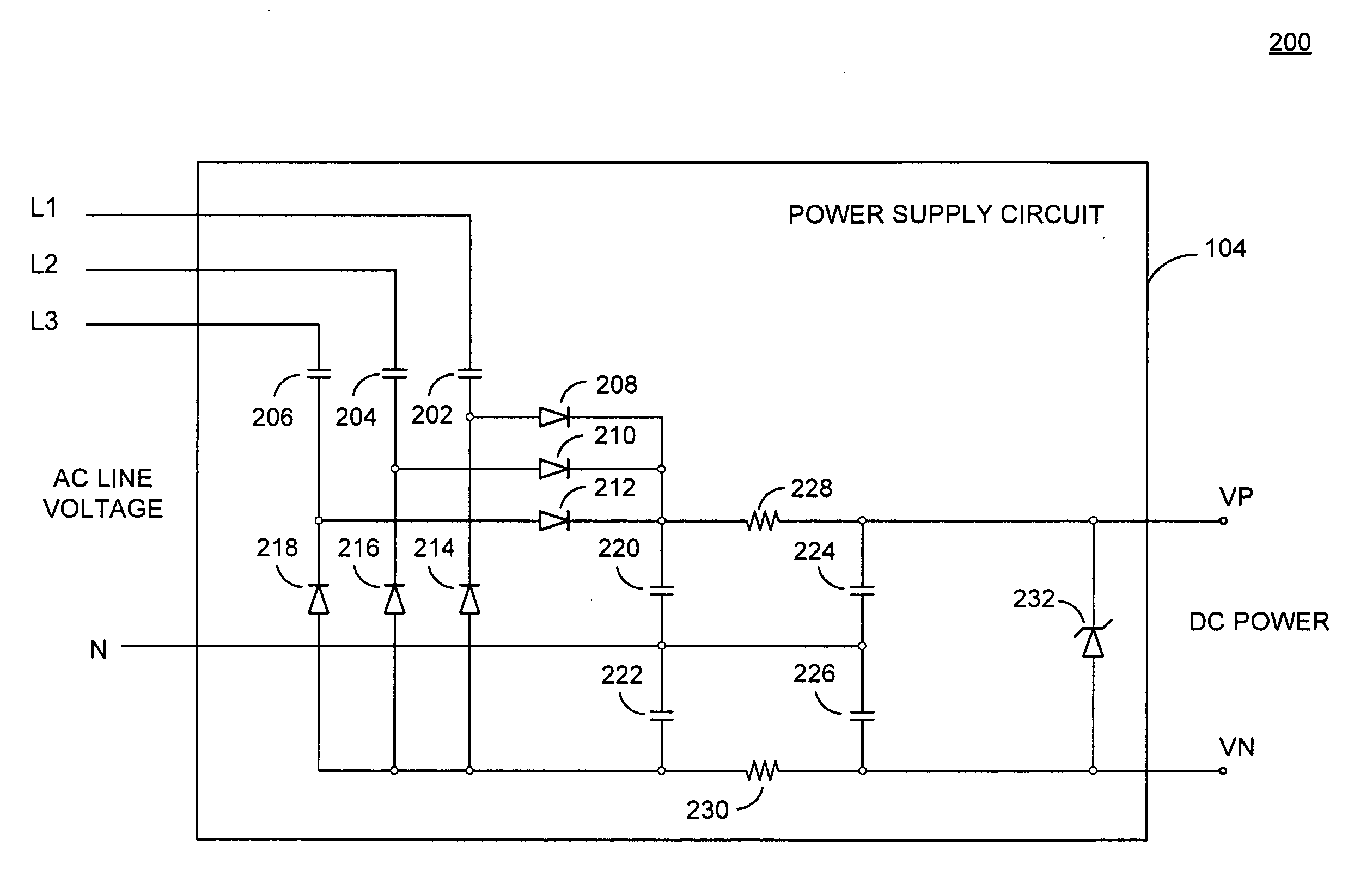
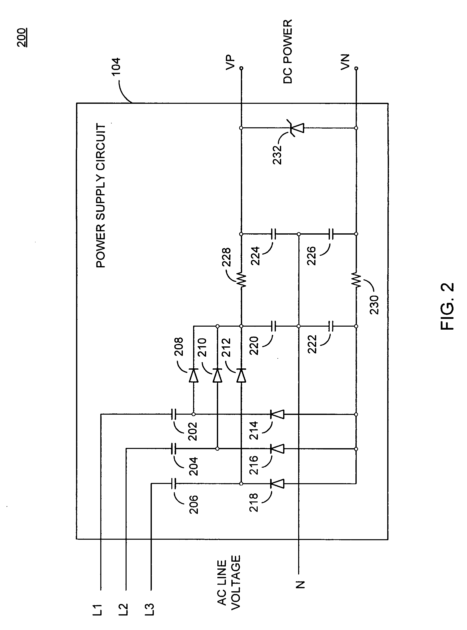
[0016]The power supply circuit 104 is coupled to each line of the grid, i.e., L1, L2, L3, and N; lines L1, L2, and L3 carry a first, a second, and a third phase, respectively, of a three-phase AC voltage on the grid (“grid voltage”), and line N provides a neutral line. The pow...


PUM


Abstract

A method and apparatus for providing AC voltage measurements. The apparatus comprises an AC voltage monitor for determining at least a first and a second voltage representing an AC voltage of an AC circuit, generating a serial data stream frame comprising data representing the at least a first and a second voltage, and transmitting the serial data stream frame.

Description

CROSS-REFERENCE TO RELATED APPLICATIONS[0001]This application claims benefit of U.S. provisional patent application Ser. No. 61 / 070,797, filed Mar. 26, 2008, which is herein incorporated in its entirety by reference.BACKGROUND OF THE INVENTION[0002]1. Field of the Invention[0003]Embodiments of the present invention generally relate to a method and apparatus for measuring AC voltages.[0004]2. Description of the Related Art[0005]In today's quest for obtaining energy from renewable resources, solar power is becoming an increasingly desirable option. Photovoltaic (PV) modules utilized in solar power systems convert energy from sunlight received into direct current (DC). The PV modules cannot store the electrical energy they produce, so the energy must either be dispersed to an energy storage system, such as a battery or pumped hydroelectricity storage, or dispersed by a load. One option to use the energy produced is to employ one or more inverters to convert the DC current into an alter...

Claims


Application Information

Patent Timeline
Patent Type & Authority Applications(United States)
IPC IPC(8): G01R19/00
CPCG01R15/22G01R1/203G01R19/0084G01R19/0092G01R19/2503
Inventor FORNAGE, MARTIN
Owner ENPHASE ENERGY
Why Eureka
Try Eureka