Liquid discharge head and recording apparatus having the same

a liquid discharge and recording apparatus technology, applied in the direction of printing, inking apparatus, etc., can solve the problems of not being able to use recording, affecting recording, and increasing the cost, and achieve the effect of stable recording

Active Publication Date: 2009-10-01
CANON KK
View PDF4 Cites 14 Cited by
  • Summary
  • Abstract
  • Description
  • Claims
  • Application Information

AI Technical Summary

Benefits of technology

[0017]The present invention provides an inkjet recording head capable of stable recording even if bubbles are generated in a liquid chamber.
[0019]With the configuration of the present invention, bubbles can easily communicate through the communicating portion between the liquid introduction passage and the liquid chamber, so that the bubbles can easily move from the liquid chamber to the liquid introduction passage. Accordingly, a liquid discharge head can be provided in which the influence of the bubbles in the liquid chamber on recording can be reduced so that stable recording can be performed.

Problems solved by technology

Thus, if bubbles remain or are left in the liquid chambers for a long time, they can exert a bad influence on recording.
As described above, it is possible to reduce bubbles remaining in the liquid chambers by suction recovery; however, conventional recording heads need frequent suction recovery, thus posing the problem of wasting ink every suction recovery, so that it cannot be used for recording.
This is, however, not desirable, because this increases the area of the recording element substrate, thus increasing the cost.

Method used


Image

  • Liquid discharge head and recording apparatus having the same
  • Liquid discharge head and recording apparatus having the same
  • Liquid discharge head and recording apparatus having the same

Examples


first embodiment

[0090]A first embodiment will be described with reference to FIGS. 5A, 5B, 6A, 6B, 6C, and 10B.

[0091]As shown in FIG. 10B, this embodiment has therein ink containing portions H2011 to H2013 for holding cyan, magenta, and yellow inks, like common inkjet recording heads, and independent ink supply paths for introducing the inks into the individual ink supply ports H1102 in the recording element substrate H1101.

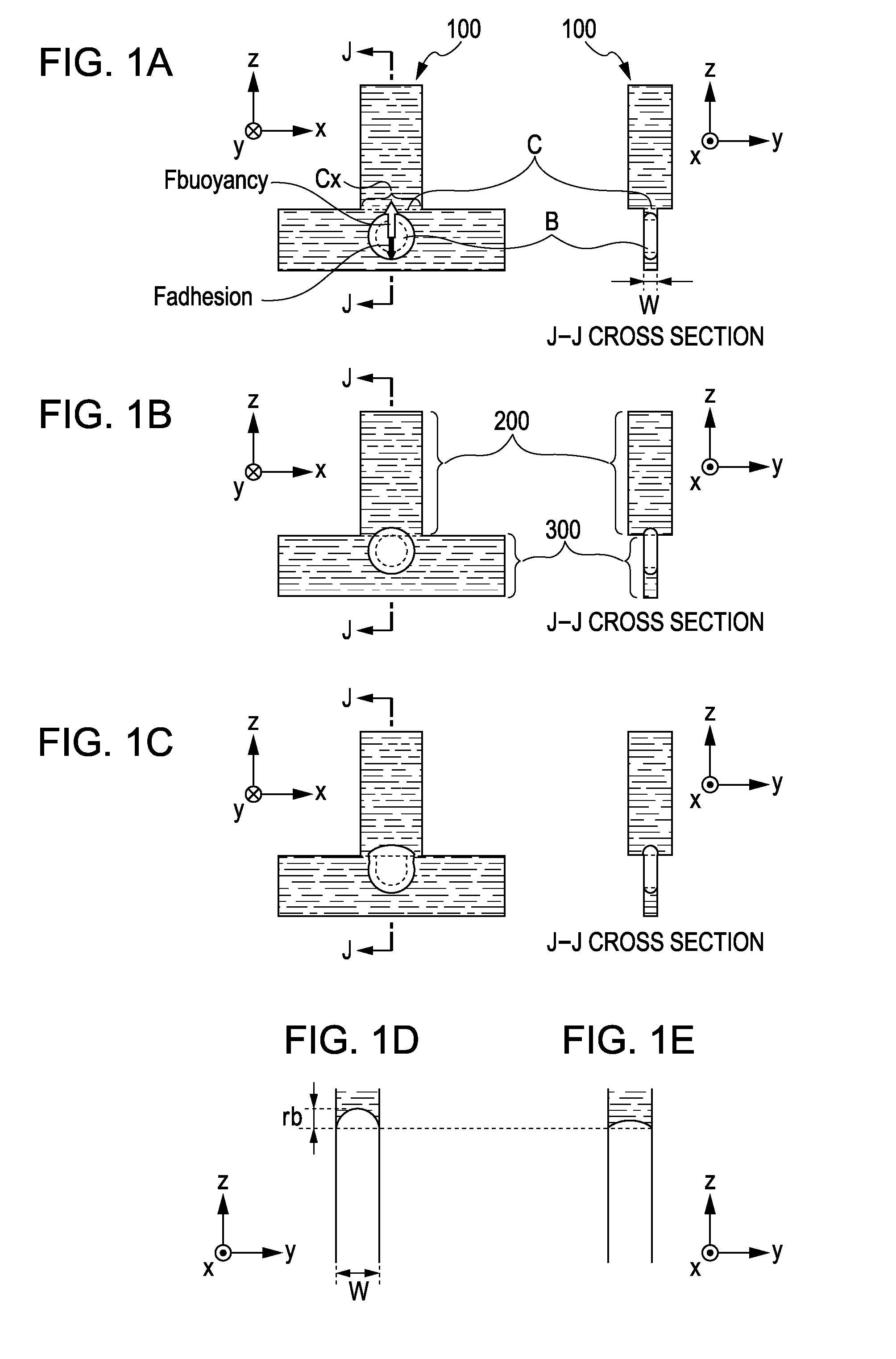
[0092]FIG. 5A is a perspective view of a cross section of the ink tank H1501 (a covering member H1901 and so on are not shown for clarification of description).

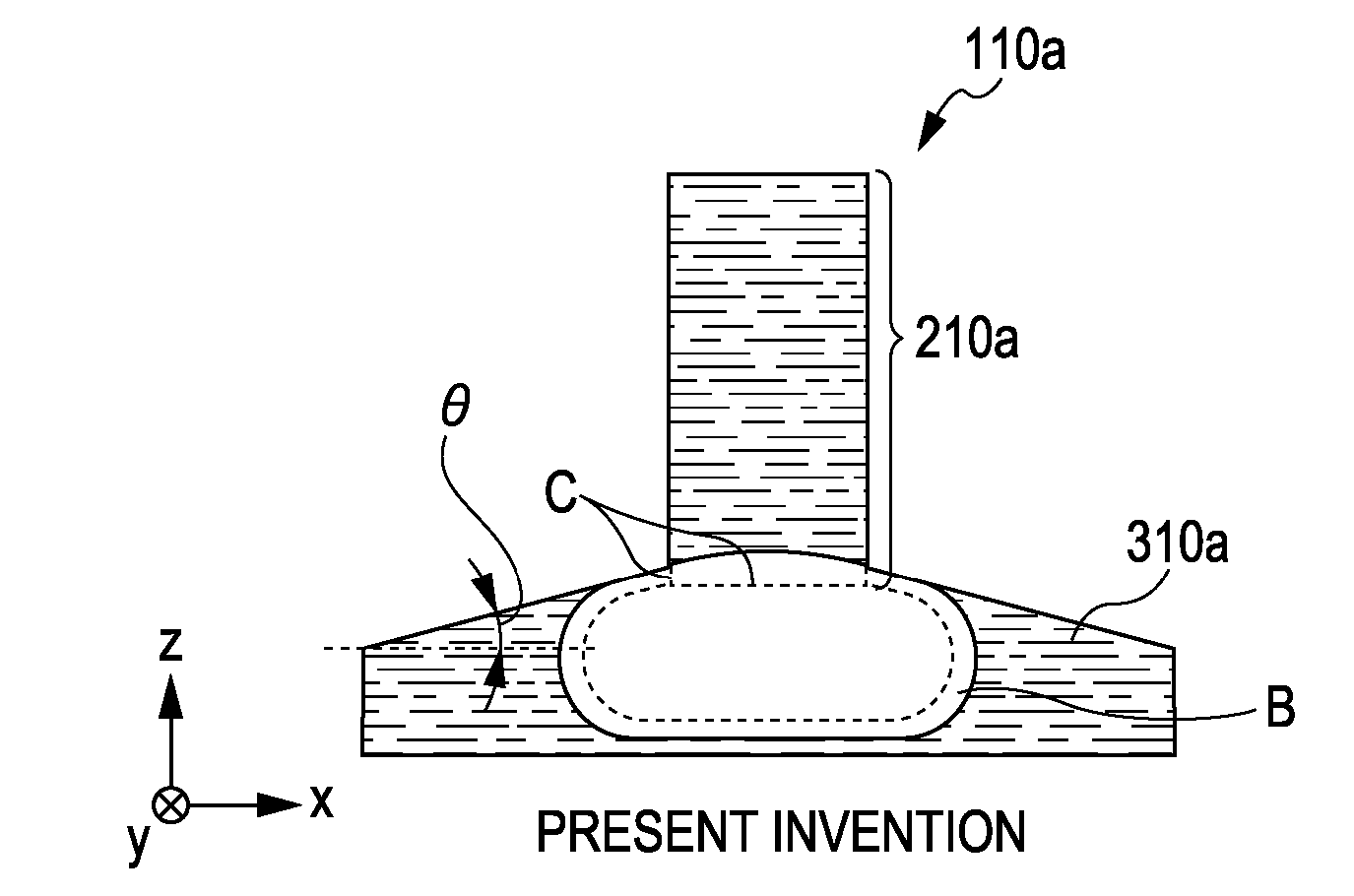
[0093]FIG. 5B shows an enlarged view of a part VB in FIG. 5A to describe the shape of the ink supply path of this embodiment in detail. As shown in the drawing, the connecting portion between a liquid chamber H2211 having a given width W and an ink introduction passage H2111 that is shorter than the length of the liquid chamber H2211 and longer than the liquid-chamber width W in the x-direction is referred to as a communi...

third embodiment

[0110]A third embodiment will be described with reference to FIGS. 8A, 8B, 9A, 9B, 9C, and 11.

[0111]While the first and second embodiments have been described as related to the configuration of an inkjet recording head having a recording element substrate capable of ejecting three colors of ink, the third embodiment will be described as related to a four-color inkjet recording head.

[0112]In this embodiment, ink supply paths applied to the recording head H1002 capable of ejecting four colors of ink, shown in FIG. 11, will be described. As shown in the drawing, the ink tank H1502 has therein ink containing portions H2031 to H2034 for holding cyan, magenta, yellow, and black inks. The ink supply ports in a recording element substrate (not shown) having four discharge port arrays have independent ink supply paths for introducing the inks into the individual ink supply ports.

[0113]FIG. 9C shows an example in which four ink supply paths S31 to S34 are appropriately arranged in the ink tan...

second embodiment

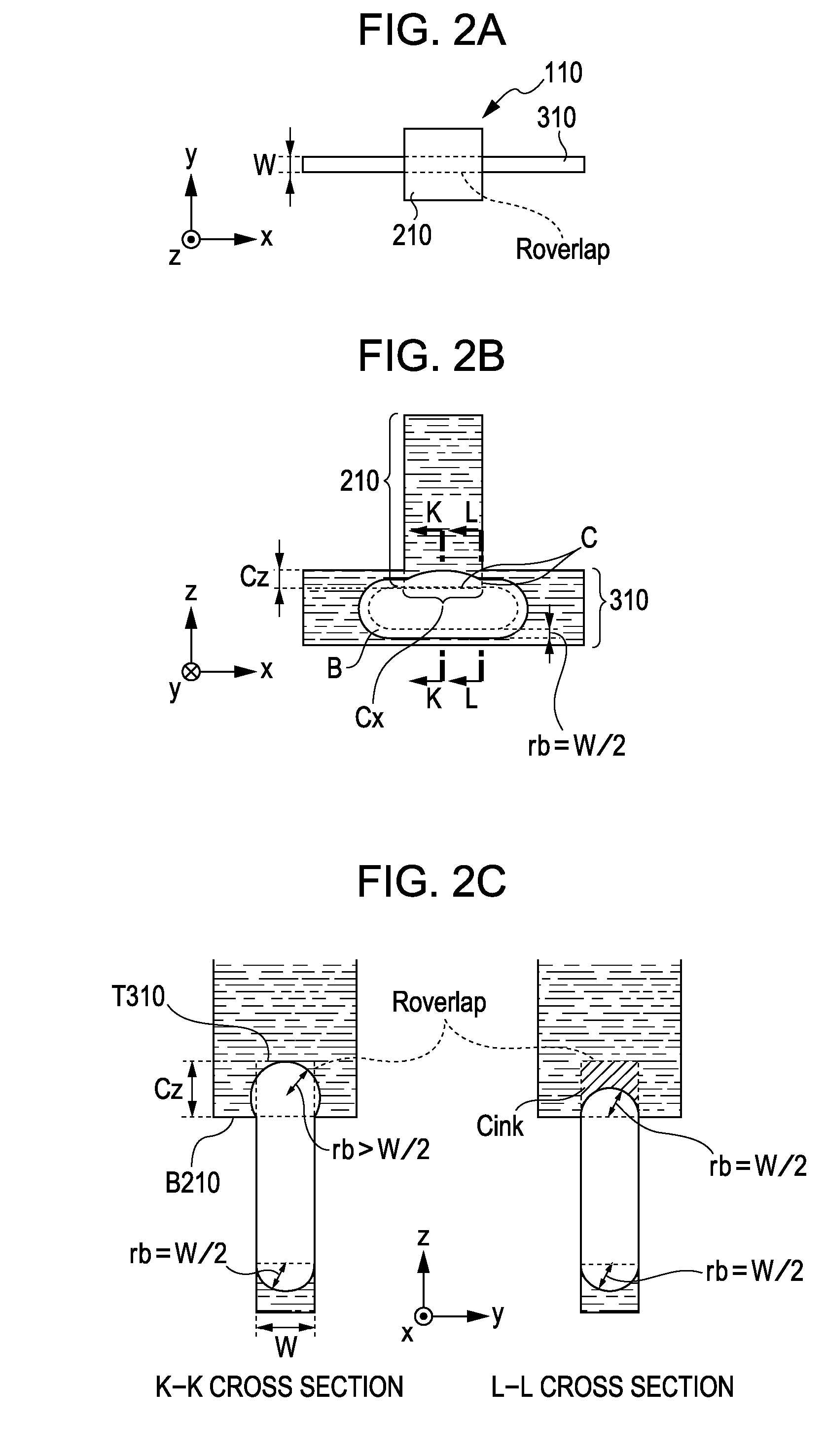
[0119]Even if the z-direction length Cz3 of the vertical surface is short, the same advantages as the second embodiment can be offered provided that Cz3>W / 2 is satisfied.

[0120]As described above, even if the communicating portion C is constituted by two surfaces, bubbles can easily communicate through the communicating portion C, as in the first and second embodiments, and furthermore, an ink communicating state can be maintained on at least one surface.

[0121]Although the first to third embodiments have been described taking a vertical surface and a horizontal surface as surfaces that constitute the communicating portion C, surfaces to which the ink introduction passage and the liquid chamber connect may not necessarily be vertical or horizontal. Surfaces that constitute the communicating portion C may be two or more. That is, it is sufficient that the communicating portion C have a projection plane viewed from the x-direction and a projection plane viewed from the x-direction, and ...


PUM


Abstract

A liquid discharge head includes a discharge port array having discharge ports for discharging liquid, a liquid chamber for supplying liquid to the discharge port array, and a liquid introduction passage for introducing liquid to the liquid chamber. A vertical cross section of the liquid chamber has an elongated shape. The liquid introduction passage is wider than the liquid chamber in a width direction of the elongated shape. A communicating portion is longer than a width of the liquid chamber and shorter than the liquid chamber, and is projecting from the liquid introduction passage for the liquid chamber. A bottom of the liquid introduction passage is disposed at a lower position than a top of the liquid chamber in the communicating portion, and a distance between the top and the bottom is longer than half of the width of the liquid chamber.

Description

BACKGROUND OF THE INVENTION[0001]1. Field of the Invention[0002]The present invention relates to a liquid discharge head that ejects liquid, such as ink, and a recording apparatus having the same.[0003]2. Description of the Related Art[0004]A known example of a liquid discharge head is an inkjet recording head (hereinafter referred to as a recording head). The recording head is provided with a recording element substrate for ejecting liquid such as ink. Recording is performed such that ink held and stored in an ink tank is supplied to the recording element substrate through an ink supply channel.[0005]In a color printer that uses more than one kind of ink, a recording element substrate to which the more than one kind of ink is supplied is mounted to a recording head. As printers are increasingly dropping in price in recent years, efforts are being made to reduce the areas of, particularly, the high-cost recording element substrates.[0006]As shown in FIG. 12, a recording element subs...

Claims


Application Information

Patent Timeline
Patent Type & Authority Applications(United States)
IPC IPC(8): B41J2/135
CPCB41J2/14145B41J2202/07B41J2/17513
Inventor KUROBE, RYOICHIRO
Owner CANON KK
Why Eureka
Try Eureka