Eureka AIR delivers breakthrough ideas for toughest innovation challenges, trusted by R&D personnel around the world.

Optical recording apparatus

Inactive Publication Date: 2005-11-03
TAIYO YUDEN KK
View PDF9 Cites 13 Cited by
  • Summary
  • Abstract
  • Description
  • Claims
  • Application Information

AI Technical Summary

Benefits of technology

[0020] Preferably, the test pattern used at this time is a pattern in which information needed to test quality appears efficiently so that the test will be completed in a short time using a small recording area. Furthermore, in order to allow stable recording over a range from low speed to high speed, it is effective to include a pattern that stabilizes servo sampling in addition to a pattern needed for testing quality. Furthermore, it is also effective to change test pattern between low speed and high speed or in accordance with recording speed.
[0024] By selecting an optimal characteristic value from a plurality of characteristic values obtained under a plurality of recording conditions, a more suitable characteristic value for the drive is used as a reference. Thus, the accuracy of criterion of recording quality is improved, and an optimal condition can be chosen even if a drive and a medium do not match well. A system reference value, threshold, or margin that serves as a criterion of recording quality is preferably stored in a non-volatile memory provided in the drive.
[0026] The criterion is preferably a value that is specific to the optical recording apparatus or a value that is specific to a type of the optical recording apparatus. When the criterion is a value that is specific to each apparatus, variation among individual apparatuses is absorbed as much as possible. When the criterion is a value that is specific to each type of apparatus, the number of setting steps is reduced compared with the case where the value is apparatus specific. Alternatively, the criterion may be an average value of system reference values obtained with a plurality of optical recording apparatuses. This also serves to reduce the number of setting steps.
[0033] For example, when a medium loaded on a drive has an extremely low sensitivity, an alert signal is issued before actual recording is carried out, and recording condition is modified suitably or recording operation is stopped, avoiding recording at a low sensitivity that prohibits playback or that causes low-quality playback. Accordingly, loss of a media area due to inappropriate recording is avoided.
[0038] Preferably, an amount of margin that is determined according to positional relationship between the approximated curve and the threshold is used as the criterion of recording quality. By using the magnitude of the amount of margin as a reference, it is possible to determine recording quality more precisely. For example, since recording quality tends to be good when the amount of margin is large while recording quality tends to be not good when the amount of margin is small, it is possible to deny recording by the drive on a medium that fails to provide a prescribed amount of margin. As just described, by determining the level of recording quality based on the magnitude of the amount of margin and making recording condition in accordance with recording quality, it is possible to implement a recording system that is insusceptible to various effects such as disturbance, variation among drives, and variation among media.

Problems solved by technology

As described in Japanese Unexamined Patent Application Publication No. 2001-126254, if the reference value is a value obtained based on playback characteristics, it is not possible to standardize various factors that affect recording, so that the accuracy of determining recording quality is insufficient.

Method used


Image

  • Optical recording apparatus
  • Optical recording apparatus
  • Optical recording apparatus

Examples


Embodiment Construction

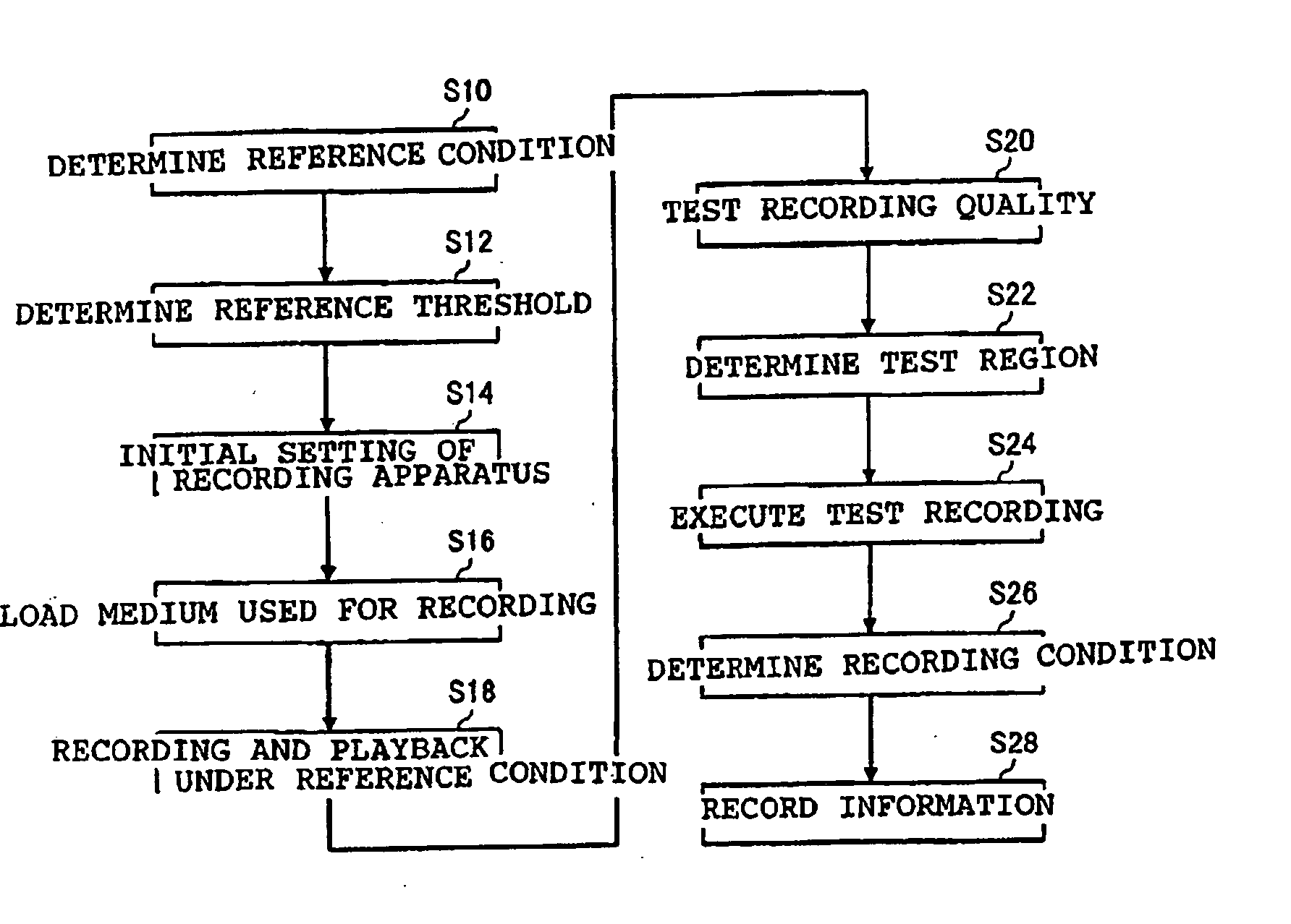
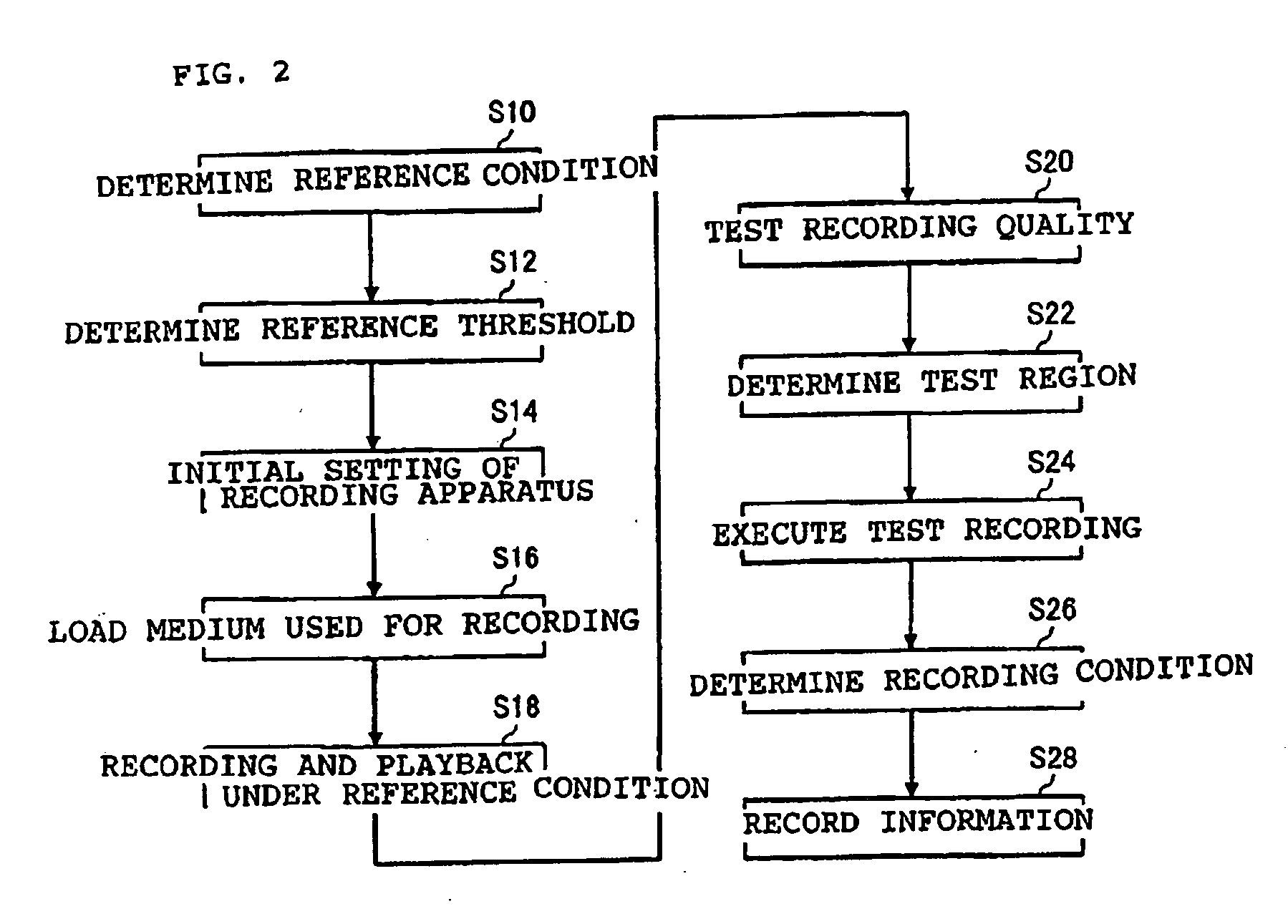
[0075] An optical-information recording apparatus according to an embodiment of the present invention will be described with reference to the drawings. The present invention can be accomplished in various ways including, but not limited to, the foregoing embodiments

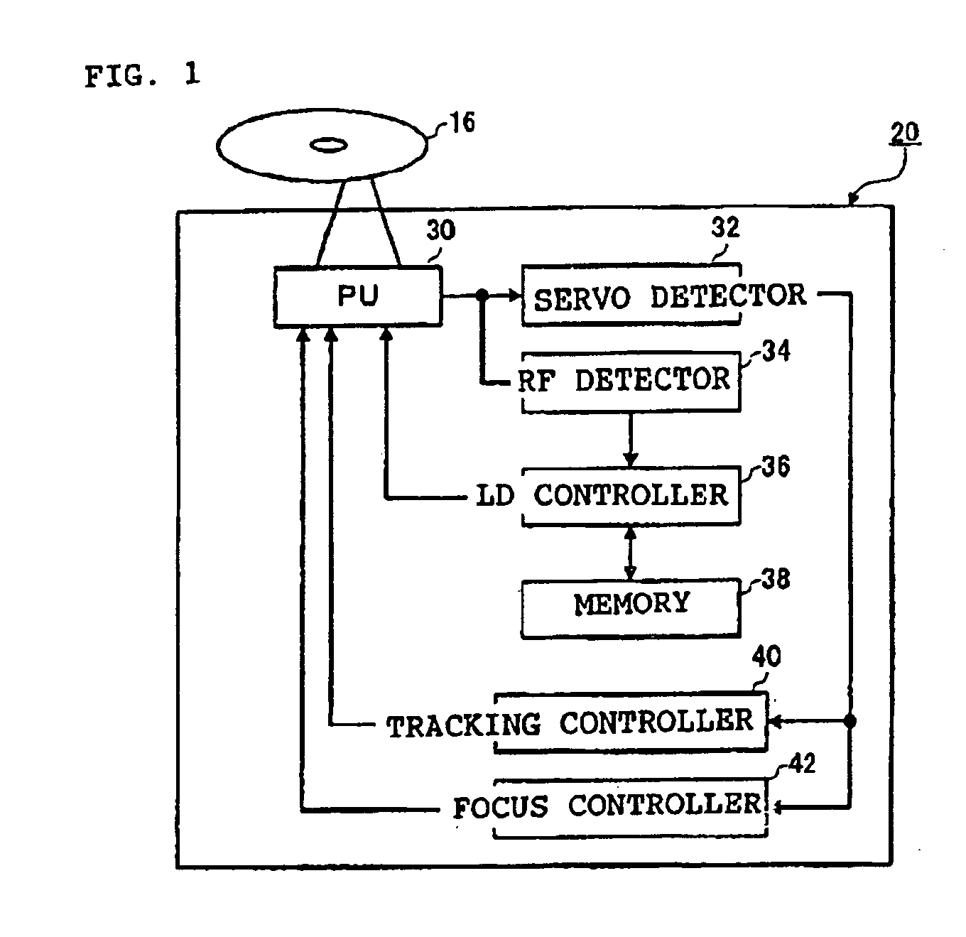
[0076]FIG. 1 is a block diagram showing the overall construction of a recording system including a medium and a drive according to an embodiment of the present invention. Referring to FIG. 1, the recording system includes a drive 20 according to this embodiment, and a medium 16 for recording by the drive 20. The medium 16 can be an optical-information recording medium, for example, a dye-based medium such as a CD-R or DVD-R, or a phase-change medium such as a CD-RW or DVD-RW.

[0077] As shown in FIG. 1, the drive 20 includes a pickup 30 that forms an optical system for irradiating the medium 16 with laser beams, a servo detector 32 for detecting geometric information of a control position of the pickup 30, an RF detector ...


PUM


Abstract

Several drives individually carry out recording and playback with a reference medium that serves as a reference for quality for various media, obtaining characteristic values. The characteristic values are multiplied by a predetermined coefficient to obtain thresholds, and the thresholds are stored in predetermined storage areas of the respective drives. When information is to be recorded on a medium, recording and playback are carried out with the medium under a plurality of recording conditions involving variation in power or pulse width, thereby obtaining characteristic values. Then, an approximated curve is obtained from the characteristic values. The quality of recording on the medium is tested based on an amount of margin that is determined according to positional relationship between the approximated curve and the threshold.

Description

BACKGROUND OF THE INVENTION [0001] 1. Field of the Invention [0002] The present invention relates to optical recording apparatuses such as optical disk recording apparatuses. More specifically, the present invention relates to an optical recording apparatus provided with a reference value that is useful in testing recording quality. [0003] 2. Description of the Related Art [0004] In recording of data on optical information recording media such as CD-R and DVD-R (hereinafter referred to as a medium), matching between a medium on which data is to be recorded and a recording apparatus (hereinafter referred to as a drive) used for recording differs among combinations of a medium and recording apparatus. This is due to factors relating to the medium such as variation in optimal recording condition due to difference in the type of recording material of the medium or due to variation that occurs in film formation during manufacturing, and due to factors relating to the drive such as variat...

Claims


Application Information

Patent Timeline
IPC IPC(8): G11B7/00G11B7/0045G11B7/125G11B7/1267G11B20/00G11B20/18
CPCG11B7/1267G11B7/00456
Inventor KAKIMOTO, HIROYASEKIGUCHI, MITSUO
Owner TAIYO YUDEN KK
Why Eureka
Eureka Blog
Learn More