Spindle motor, information recording and reading device with same, and spindle motor mfg. method

A technology for spindle motor and information recording, which is applied in the directions of information recording, magnetic recording, and information storage on magnetic disks, and can solve the problems of inability to improve the coaxiality of inner and outer diameters, increase in cost, and large processing equipment.

Inactive Publication Date: 2003-02-19
PANASONIC CORP
View PDF2 Cites 12 Cited by
  • Summary
  • Abstract
  • Description
  • Claims
  • Application Information

AI Technical Summary

Problems solved by technology

[0023] (4) Increase the viscosity of the oil
[0028] (4) When the viscosity of the lubricating oil increases, the loss of the bearing will increase extremely in the low temperature area
However, when the inner circumference is removed or the coaxiality of the inner and outer diameters is corrected in finishing after steel ball rolling, the outer circumference may be damaged, and the inner circumference cannot be processed on the basis of the outer diameter, thus, the inner and outer diameters The coaxiality cannot be improved
Alternatively, when a radial bearing is formed by forming grooves for generating dynamic pressure on the inner circumference of the bearing housing, high forming accuracy is required for the bearing housing having the dynamic pressure generating grooves, which increases the cost
[0031] Specifically, when the rotating shaft is not simply cylindrical but is integrated with the rotor hub to fix the disk plate, a special holding tool is required to form and process grooves for generating dynamic pressure in the rotating shaft, so that , the processing device becomes larger and more complicated, and the processing cost increases

Method used


Image

  • Spindle motor, information recording and reading device with same, and spindle motor mfg. method
  • Spindle motor, information recording and reading device with same, and spindle motor mfg. method
  • Spindle motor, information recording and reading device with same, and spindle motor mfg. method

Examples


no. 1 example

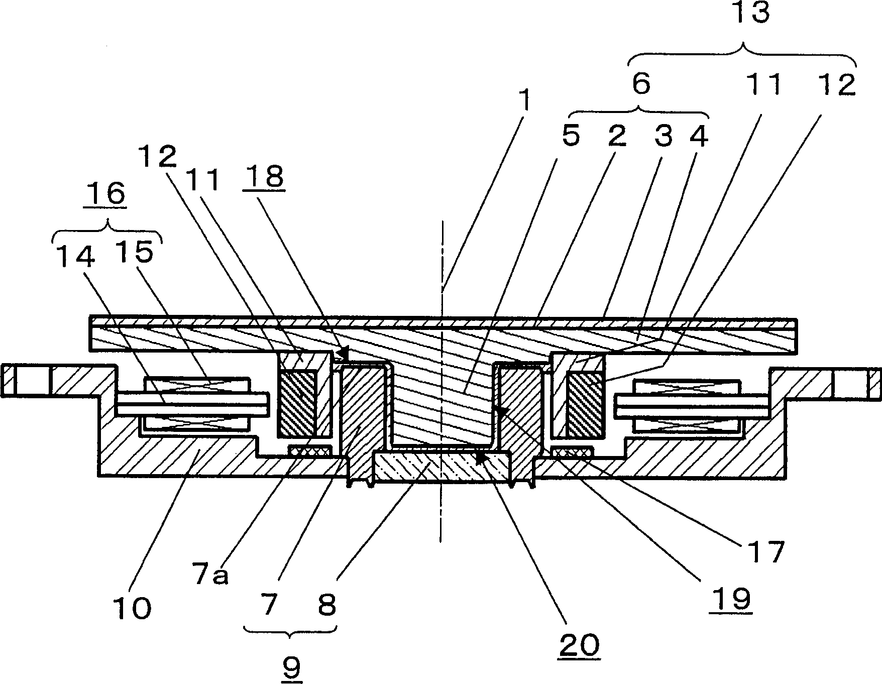
[0109] Figure 1A and figure 2 is a schematic diagram of the main components of the spindle motor, which shows the first embodiment of the present invention, specifically, Figure 1A is a sectional view taken along the section of the main part of the spindle motor, figure 2 for Figure 1A Partial enlarged view of the bearing part in , while Figure 3A is a view from the top of a part that excludes the Figure 1A Rotating disk and rotor yoke in .

[0110] Figure 1A A rotating magnetic disk 6 is shown, which is integrally formed by a magnetic disk device 4 and a solid cylindrical rotating shaft 5, wherein the magnetic disk device 4 forms a Information recording medium layer 3. The magnetic disk device 4 and the rotary shaft 5 may be made of separately manufactured members, which may be assembled by insert molding, adhering, to form the rotary magnetic disk 6 by using an adhesive, hot-melt, or other methods. A small gap is formed between the inner circumference of the cylin...

no. 2 example

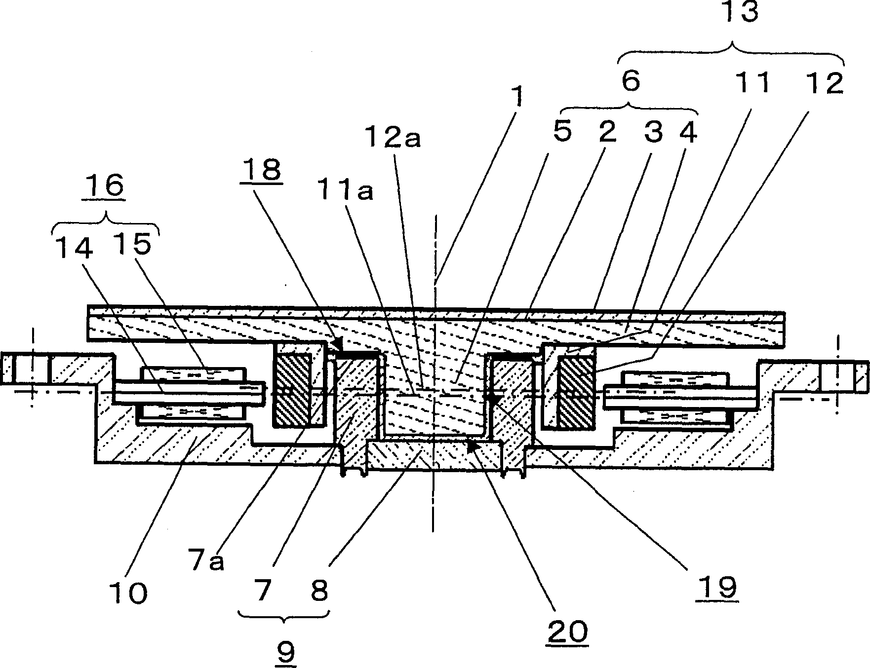
[0149] Figure 14 A cross-sectional view of main parts for illustrating a spindle motor according to a second embodiment of the present invention. exist Figure 14 In , the reference numerals of the elements corresponding to the constituent elements in the first embodiment are the same as Figure 1Ain the same. The spindle motor of the second embodiment differs from the first embodiment in that the rotary magnetic disk is a structure in which the magnetic disk device and the cylindrical rotating cylinder portion are integrally formed, and the rotary magnetic disk is supported around a bearing fixed to the base as the center of rotation. The central axis of the shaft rotates.

[0150] exist Figure 14 Among them, the rotary magnetic disk 6 is composed of a magnetic disk device 4 and a rotating cylindrical part 141, wherein the magnetic disk device 4 has an information recording medium layer (not shown) on the main plane perpendicular to the rotation center 1, and the rotatin...

no. 3 example

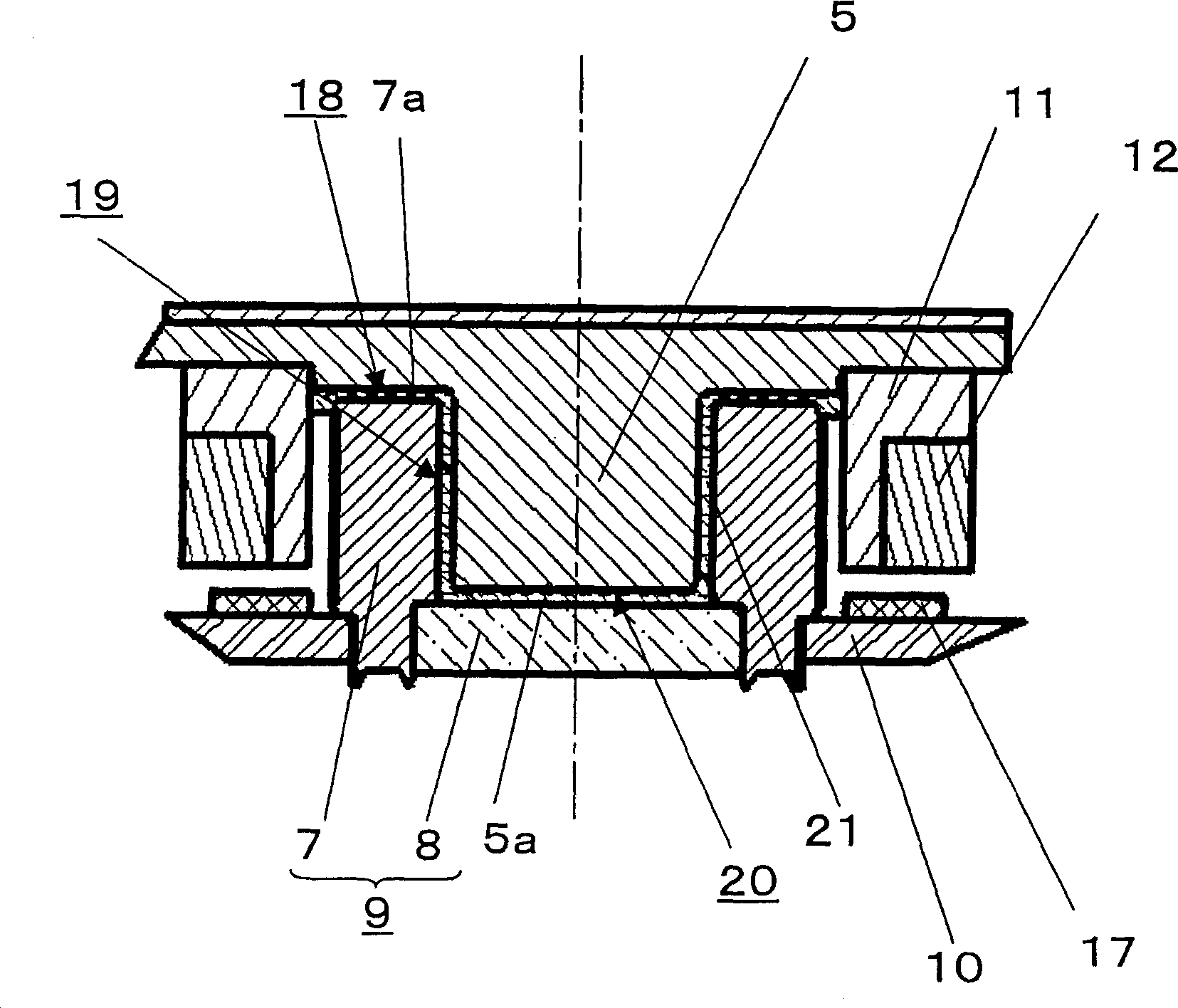
[0170] Figure 18 and FIG. 19 is a view illustrating the structure of main parts of a spindle motor according to a third embodiment of the present invention, specifically, Figure 18 Fig. 19 is a partial enlarged view of the vicinity of the central portion of the spindle motor for the purpose of showing a cross-sectional view of the structure of the main parts of the spindle motor. exist Figure 18 and Figure 19, with Figure 1A components corresponding to the Figure 1A Indicated by the same symbols.

[0171] exist Figure 18 , through the near as Figure 19A A first lubricant groove 181 can be formed in the rotor yoke 11 by cutting an annular groove close to the triangular cross-section of the magnetic disk device 4 at the inner peripheral side of the shown bearing housing 7 . In addition, a taper 182 is formed from the edge of the rotor yoke 11 to the groove for forming the first lubricant groove 181, and the diameter of the taper becomes wider near the magnetic disk de...


PUM


Abstract

A spindle motor of small size, thin type, high reliability, and high performance suited to an information recording and reproducing apparatus is presented. Specifically, a rotary disk is composed by integrally forming a disk board, and a rotary shaft of spindle motor, and a bearing is composed by forming dynamic pressure generating grooves in the rotary shaft of the rotary disk. As a result, small size and thin structure are realized, surface deflection of the disk during rotation of the spindle motor, and its axial center deflection are substantially decreased, and moreover the recording density is enhanced, the number of constituent parts is curtailed, and the cost is saved.

Description

field of invention [0001] The present invention relates to a device for recording and reading information by using an information recording medium, wherein the information recording medium may be a magnetic disk or an optical disk. In particular, the present invention relates to a hydraulic bearing spindle motor most suitable for high-density recording and reading information , an information recording and reading device having such a hydraulic bearing spindle motor and a manufacturing method of the hydraulic bearing spindle motor. Background of the invention [0002] Recently, various information applications are used, and it is required that the storage capacity of a magnetic disk device can be increased, and there is an increasing demand for high-density recording. With this tendency, higher reliability and rotational accuracy of the disk are required, and in order to increase the recording density, the shaft rotation deviation of the spindle motor bearing unit used in th...

Claims


Application Information

Patent Timeline
Patent Type & Authority Applications(China)
IPC IPC(8): G11B19/20
CPCF16C17/107G11B19/2009F16C2370/12F16C33/14F16C2220/44F16C2220/66F16C2223/08
Inventor 野田宏充小幡茂雄
Owner PANASONIC CORP
Why Eureka
Try Eureka