Color-filter manufacturing method and color-filter manufacturing apparatus

a technology of color filter and manufacturing method, applied in the field of color filter manufacturing, can solve the problems of high manufacturing cost, failure to manufacture high-quality color filter, and difficulty in finer color filter, and achieve the effect of high fineness and low cos

a technology of color filter and manufacturing method, applied in the field of color filter manufacturing, can solve the problems of high manufacturing cost, failure to manufacture high-quality color filter, and difficulty in finer color filter, and achieve the effect of high fineness and low cos

US20090244229A1Inactive Publication Date: 2009-10-01FUJIFILM CORP

Image

  • Color-filter manufacturing method and color-filter manufacturing apparatus
  • Color-filter manufacturing method and color-filter manufacturing apparatus
  • Color-filter manufacturing method and color-filter manufacturing apparatus

Examples


Embodiment Construction

[0043]A detailed description will be given of preferred embodiments of the color-filter manufacturing method and the color-filter manufacturing apparatus in the present invention with reference to the drawings.

[0044]First, a description will be given of a constitution of a color-filter manufacturing apparatus.

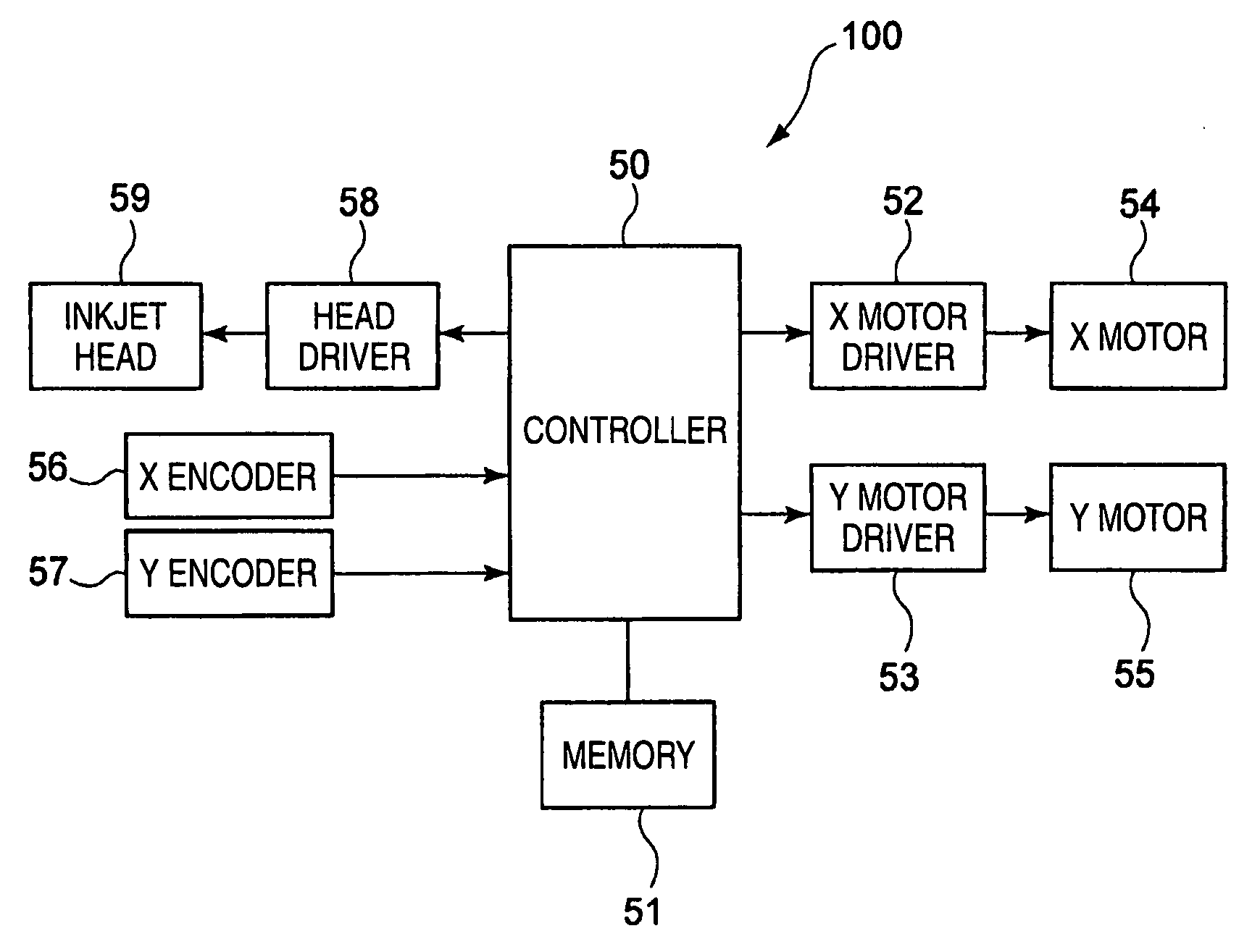
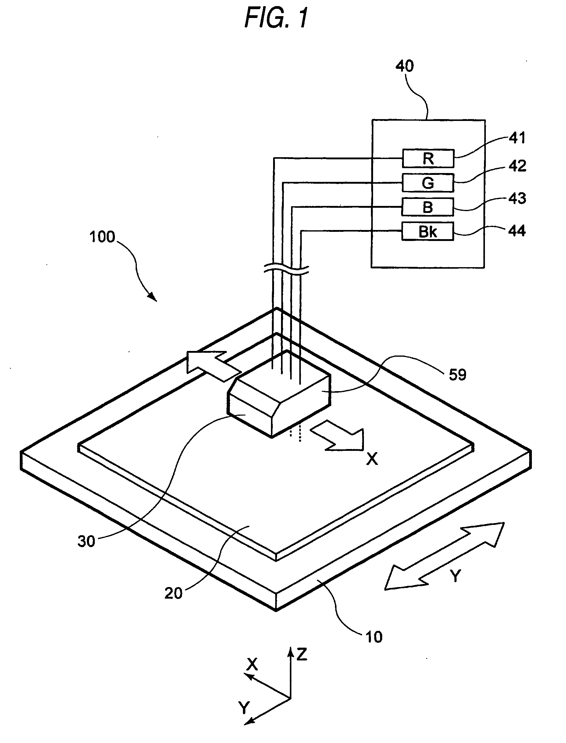
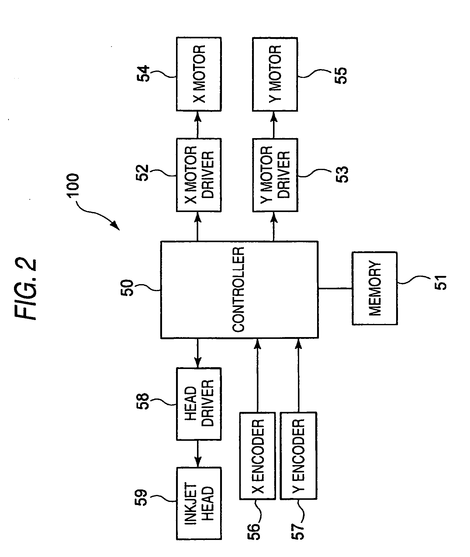
[0045]FIG. 1 is a perspective view showing one constitution example of the color-filter manufacturing apparatus for manufacturing color filters. FIG. 2 is a block diagram showing a constitution of the apparatus given in FIG. 1.

[0046]The color-filter manufacturing apparatus 100 is provided with a planar movable table 10 which may move along the Y axis direction. On the movable table 10, a transparent substrate 20 which is a substrate material of the color filter is placed. The transparent substrate 20 includes a transparent substrate such as glass or a film such as resin. Further, a head unit 30 which may move along the X axis direction orthogonal to the movement direction of th...


PUM


Abstract

A color-filter manufacturing method includes a first step in which an ink jet method is used to eject liquid inks which contain color components to form a land pattern made up of lands of light transmitting materials and a second step in which after drying of the thus ejected liquid inks, the ink jet method is used to eject a liquid ink which contains a light blocking material and the ink is allowed to permeate into a clearance between the lands, thereby forming a black matrix pattern.

Description

[0001]The present invention claims priority from Japanese Patent Application No. 2008-079317 filed on Mar. 25, 2008, the entire content of which is incorporated herein by reference.BACKGROUND OF INVENTION[0002]1. Field of the Invention[0003]The present invention relates to a color-filter manufacturing method for manufacturing color filters on a face to be formed on a substrate surface or on that on a composition surface of the substrate. The color filters have a land pattern in which a plurality of kinds of light transmitting materials which transmit specific color components are arranged numerously in a land shape and a black matrix pattern in which a light blocking material is used to fill a periphery of each land and also relates to a color-filter manufacturing apparatus.[0004]2. Description of the Related Art[0005]For example, in a display device such as a liquid crystal display panel, color filters (such as red (R), green (G) and blue (B) color filters) are arranged to display ...

Claims


Application Information

Patent Timeline
01 Oct 2009
Publication
US20090244229A1
IPC
B41J2/01
CPC
G02F1/133516; G02B5/201
Inventors
MAEDA, YASUHIKO