Developing device frame unit, developing device, process cartridge, and manufacturing method of the developing device frame unit
a technology of developing device and frame unit, which is applied in the direction of electrographic process apparatus, instruments, optics, etc., can solve the problems of increasing assembly time and increasing cos
- Summary
- Abstract
- Description
- Claims
- Application Information
AI Technical Summary
Benefits of technology
Problems solved by technology
Method used
Image
Examples
embodiment 1
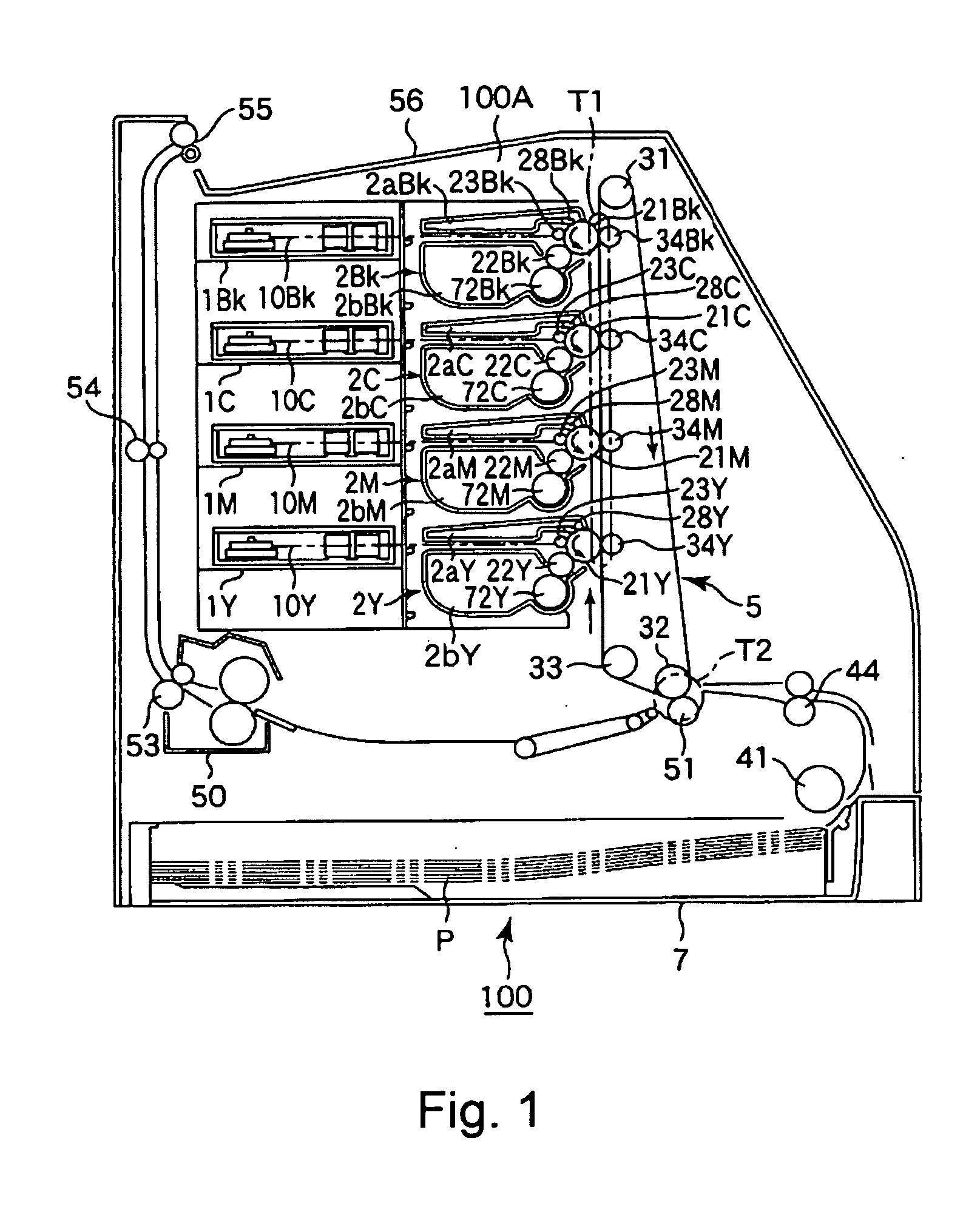
[0052]FIG. 1 shows a general arrangement of a color laser beam printer, using an electrophotographic process, as an embodiment of an image forming apparatus to which the present invention is to be applied.
(General Arrangement)
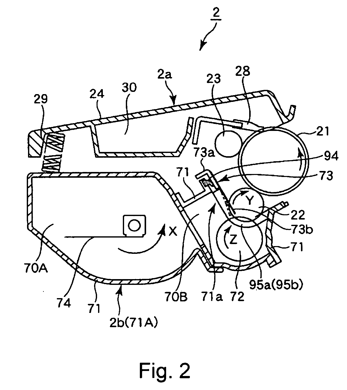
[0053]In this embodiment, the image forming apparatus 100 includes four independent process cartridges2 (2Y, 2M, 2C, 2Bk) which are detachably mountable to an apparatus main assembly 100A and are arranged vertically. In this embodiment, the process cartridges 2 (2Y, 2M, 2C and 2Bk) include image forming means for yellow (Y) toner, magenta (M) toner, cyan (C) toner, and black (Bk) toner, respectively.
[0054]In the following description, a “longitudinal direction” of the process cartridge means a direction substantially perpendicular to a direction in which the process cartridge is mounted into the main assembly 100A of the image forming apparatus (i.e., a rotational axis direction of a photosensitive drum). Further, a “left (side)” and a “right (side)” are those ...
embodiment 2
[0104]FIGS. 16(a) and 16(b) are schematic front views showing positions of the buffer portions in Embodiment 2 as another embodiment of the present invention. In Embodiment 1, the communication ports 101a and 102a are provided at the positions on the flow path of the elastomer resin material from the injection ports to the end seal members at the seal forming portion and are located in the neighborhood of the end seal members 95a and 95b.
[0105]In Embodiment 2, a buffer portion 103 enclosed by dotted lines as shown in FIG. 16(a) is provided. The buffer portion 103 also falls within the buffer portion described above in the present invention, which is disposed between the end seal members 95a and 95b and in the neighborhood of the end seal members 95a and 95b.
[0106]By this constitution, the elastomer resin material closely contacts the end seal members 95a and 95b with reliability and thereafter flows into the buffer portion 103. As a result, an effect similar to that in Embodiment ...
embodiment 3
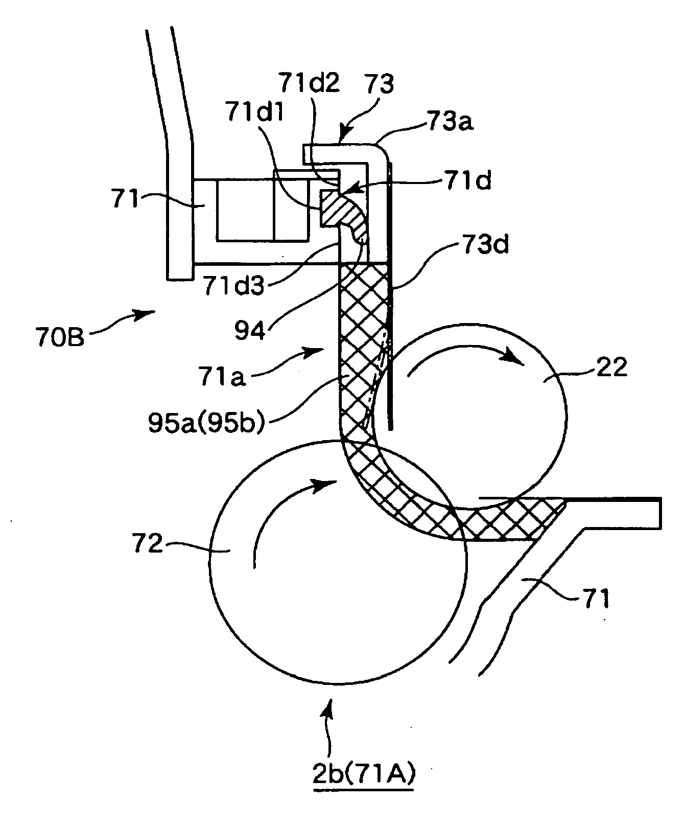
[0108]FIG. 21 is a schematic sectional view showing a buffer portion of the developing device frame unit 71A in Embodiment 3, FIG. 22 is a schematic front view showing a longitudinal end portion of the developing device frame unit 71A in a state in which an under blade seal 94 in Embodiment 3 is molded.
[0109]In Embodiment 1, the excessive portion 94a (94b) of the elastomer resin material is caused to flow into the resin material reservoir portion 101b (102b) of the buffer portion 101 (102).
[0110]In this embodiment, the resin material reservoir portion 101b (102b) is not provided for the excessive portion (protrusion) 94a (94b) of the elastomer resin material but a flow path 83a is provided to the mold 83 as shown in FIG. 21, so that the excessive portion of the elastomer resin material is caused to flow through the flow path 83a. The flow path 83a is provided at a position, as shown in FIG. 22, in which the excessive portion 94a (94b) of the elastomer resin material is caused to flo...
PUM
 Abstract
Description
Claims
Application Information
 - R&D
- Intellectual Property
- Life Sciences
- Materials
- Tech Scout
- Unparalleled Data Quality
- Higher Quality Content
- 60% Fewer Hallucinations
Browse by: Latest US Patents, China's latest patents, Technical Efficacy Thesaurus, Application Domain, Technology Topic, Popular Technical Reports.
© 2025 PatSnap. All rights reserved.Legal|Privacy policy|Modern Slavery Act Transparency Statement|Sitemap|About US| Contact US: help@patsnap.com


