Ventilating system and ventilating system control method

a technology of ventilating system and ventilation system, which is applied in the direction of ventilation system, heating type, and measurement of static/dynamic balance, etc., can solve the problems of increased head or duct resistance, reduced airflow of fans, and inability to perform tight control when applied to ventilating system structures

Inactive Publication Date: 2009-10-01
YAMATAKE HONEYWELL CO LTD
View PDF2 Cites 13 Cited by
  • Summary
  • Abstract
  • Description
  • Claims
  • Application Information

AI Technical Summary

Benefits of technology

[0017]Given the present invention, it is possible to control the speed of rotation of a fan after securing the ventilating system airflow through controlling the speed of rotation of the fan based on a static pressure within a main duct and on a target value, after setting a target static pressure value based on the airflow of the system as a whole, calculated from the air flows of venturi air

Problems solved by technology

However, in the conventional system set forth above, the following problems arise when the airflow of the fan has been reduced.
In this way, in a system that uses the conventional venturi air valves, when there is a decrease in the airflow of the fan, then the increased head or the decreased duc

Method used


Image

  • Ventilating system and ventilating system control method
  • Ventilating system and ventilating system control method
  • Ventilating system and ventilating system control method

Examples


Embodiment Construction

[0031]A form of embodiment of the present invention will be described in detail below, referencing the figures.

Ventilating System Structure

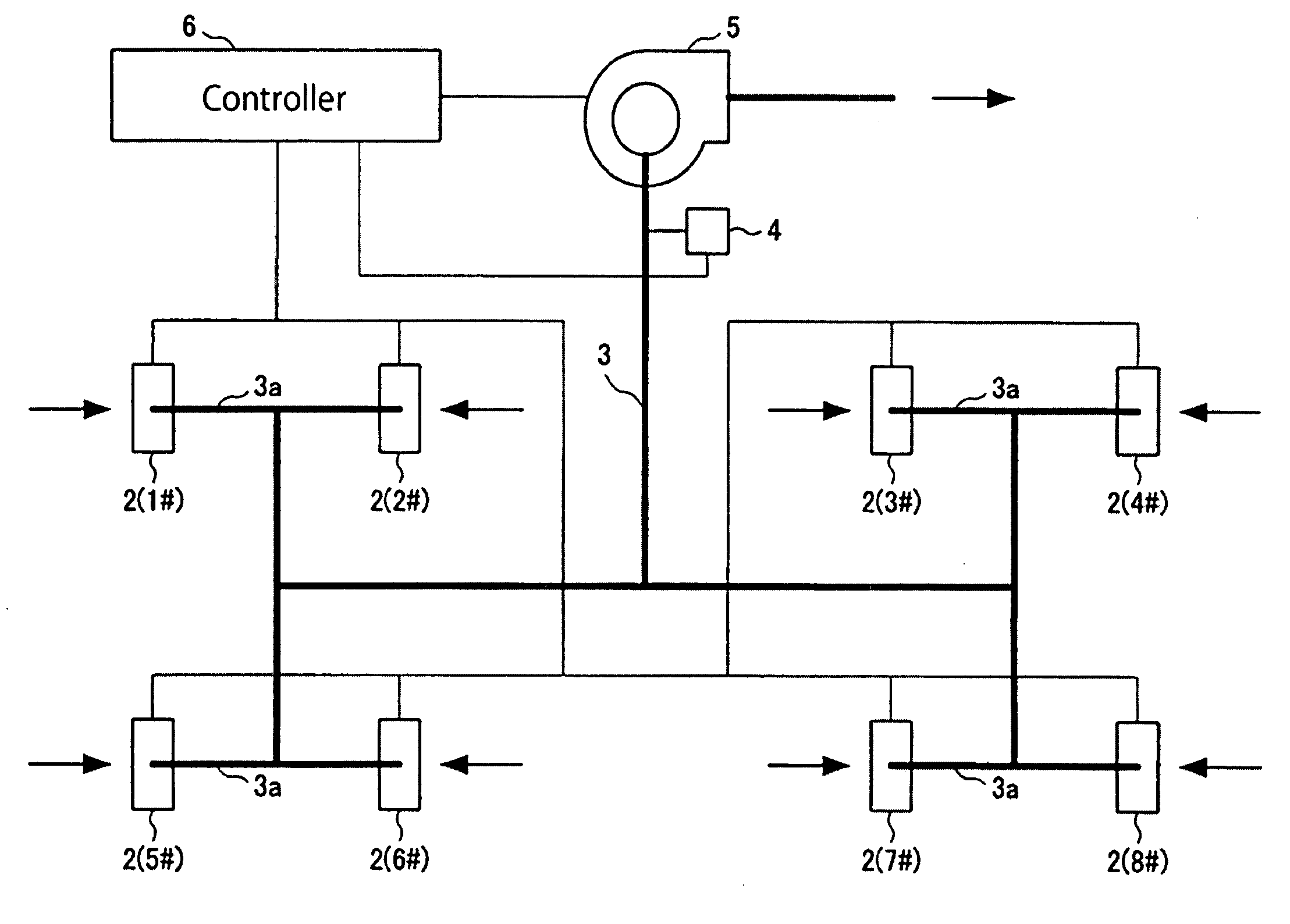
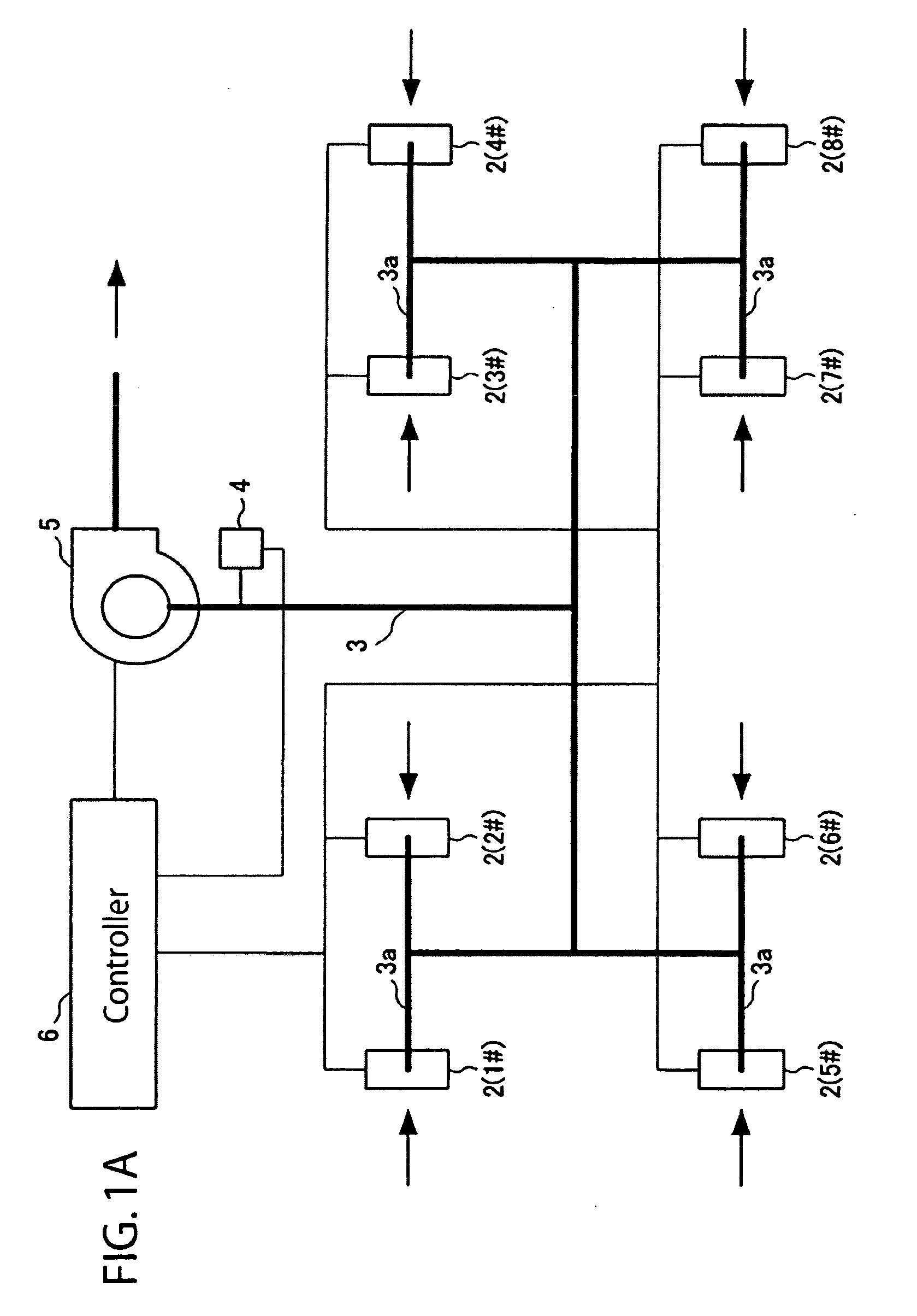
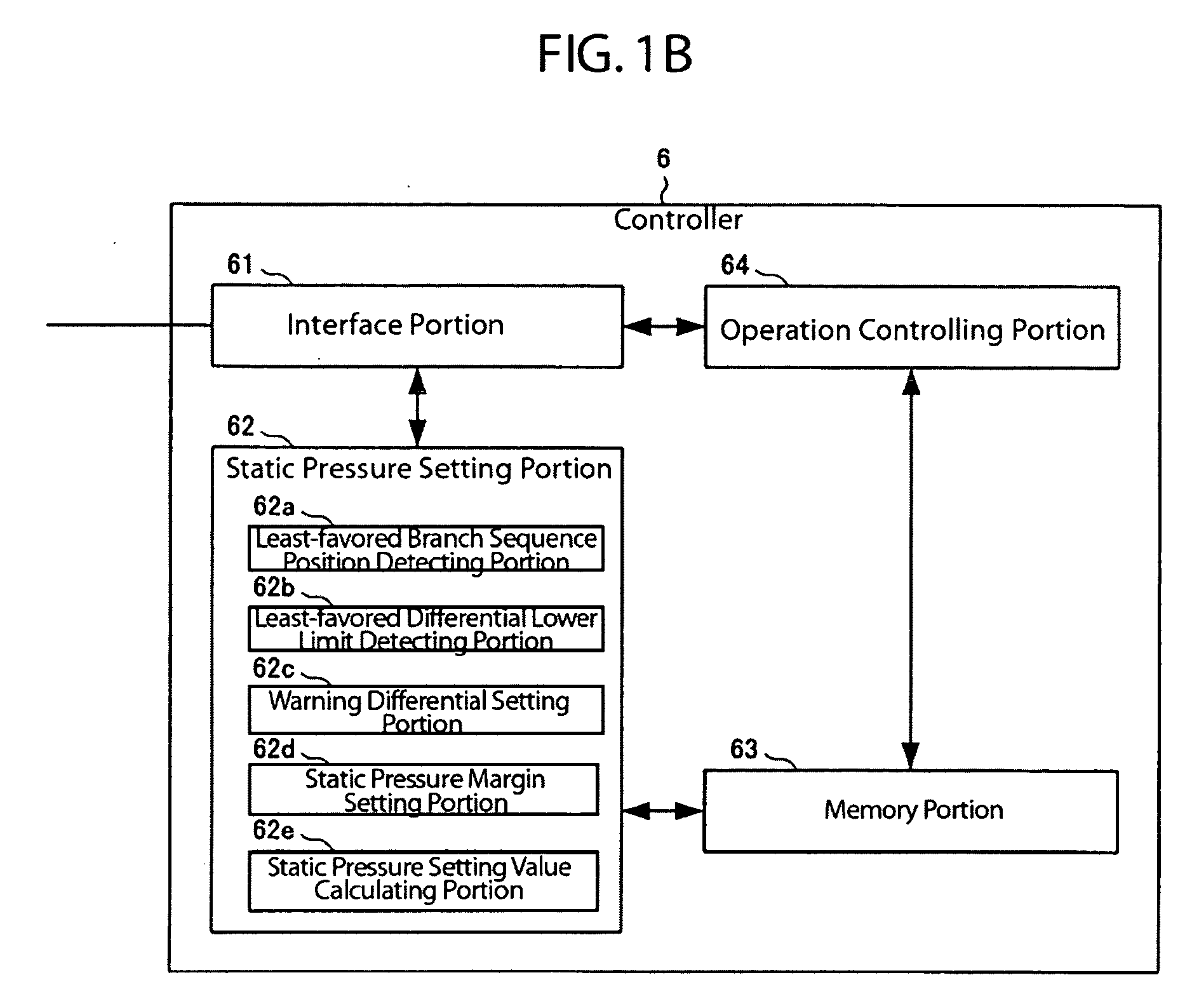
[0032]As is illustrated in FIG. 1(a) a ventilating system 1 according to the present form of embodiment is provided with: multiple fume hoods 2; a main duct 3, to which is connected multiple branched ducts 3a from each of the fume hoods 2; a pressure gauge 4 for measuring the static pressure in the main duct 3; a fan 5 connected to the output end of the main duct 3; and a controller 6 for controlling the operation of the ventilating system 1 as a whole.

[0033]The fume hoods 2 are structured from well known fume ducts that are provided with venturi air valves (not shown), and that send the air from the inside to the branched ducts 3a. These fume hoods 2 are provided with differential pressure transmitting devices (not shown) for detecting the differences in pressure before and after the venturi air valves, and for issuing a warning if the different...


PUM


Abstract

To provide a ventilating system and ventilating system control method capable of advancing energy conservation. A controller sets a static pressure setting value based on the airflow of the system as a whole, calculated from the airflow of venturi air valves of fume hoods that are operating, and controls the speed of rotation of a fan based on the static pressure setting value and the static pressure within a main duct. Doing so enables control of the speed of rotation of the fan to be performed while ensuring the airflow of the ventilating system, thus making it possible to prevent wasted motive force of the fan, even when the airflows of each of the venturi air valves are not identical and even when the changes in resistance of the branched duct system relative to the various changes in airflow are not identical, with the result that it is possible to advance energy conservation.

Description

CROSS REFERENCE TO PRIOR APPLICATIONS[0001]The present application claims priority under U.S.C. §119 to Japanese Patent Application No. 2008-086461, filed Mar. 28, 2008. The content of both applications are incorporated herein by reference in their entirety.AREA OF TECHNOLOGY[0002]The present invention relates to controlling the speed of rotation of a fan in a ventilating system, and relates to a setting value generating device for generating a setting value used in controlling the speed of rotation, relates to a setting value generating method, and to a ventilating system that uses the setting value to control the speed of rotation of a fan.BACKGROUND OF THE INVENTION[0003]In systems for strictly controlling air flows and static pressures for safety control and quality assurance in research facilities, hospitals, factories, and the like, constant airflow equipment, known as “venturi air valves” are often used in order to achieve room pressure control and local exhaust control.[0004...

Claims


Application Information

Patent Timeline
IPC IPC(8): F24F11/04F24F7/007G05B15/00
CPCF24F11/0079Y02B30/746F24F2011/0042F24F2110/40F24F11/77Y02B30/70
Inventor CHEN, XIANGYANG
Owner YAMATAKE HONEYWELL CO LTD
Why Eureka
Try Eureka