
Storage system and volume managing method for storage system

Inactive Publication Date: 2009-10-01
HITACHI LTD
View PDF37 Cites 11 Cited by
  • Summary
  • Abstract
  • Description
  • Claims
  • Application Information

AI Technical Summary

Benefits of technology

[0010]The present invention has been invented in consideration of the above points, and object of the present invention is to propose the storage system and the volume managing method of the storage system which reduces a time and a data quantity for setting information which is necessary to execute the exclusion process which is necessary when data is stored in the cluster system.
[0012]According to the present invention, the storage system and the volume managing method of the storage system can be proposed, which reduces a time and a data quantity for setting information which is necessary to execute the exclusion process which is necessary when data is stored in the cluster system.

Problems solved by technology

However, since it is necessary to execute such a synchronization process, when the service is changed, the virtual file server can not execute a process for changing another service until the synchronization process for the changed content is completed.
Thus, under the cluster circumstance, as the number of nodes becomes larger, it takes a longer time for the synchronization process, and it takes a longer time until another process can be started.

Method used


Image

  • Storage system and volume managing method for storage system
  • Storage system and volume managing method for storage system
  • Storage system and volume managing method for storage system

Examples


first embodiment

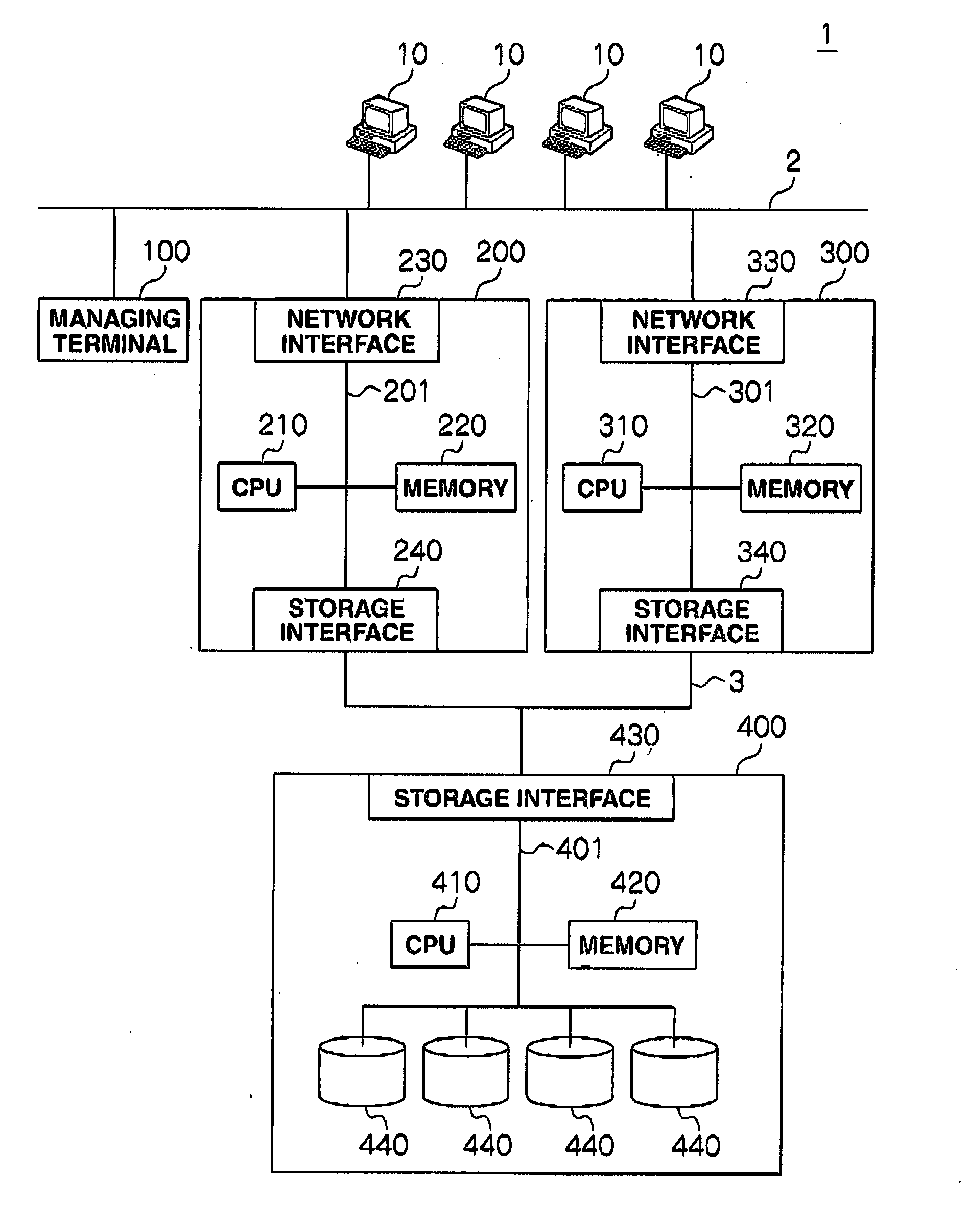
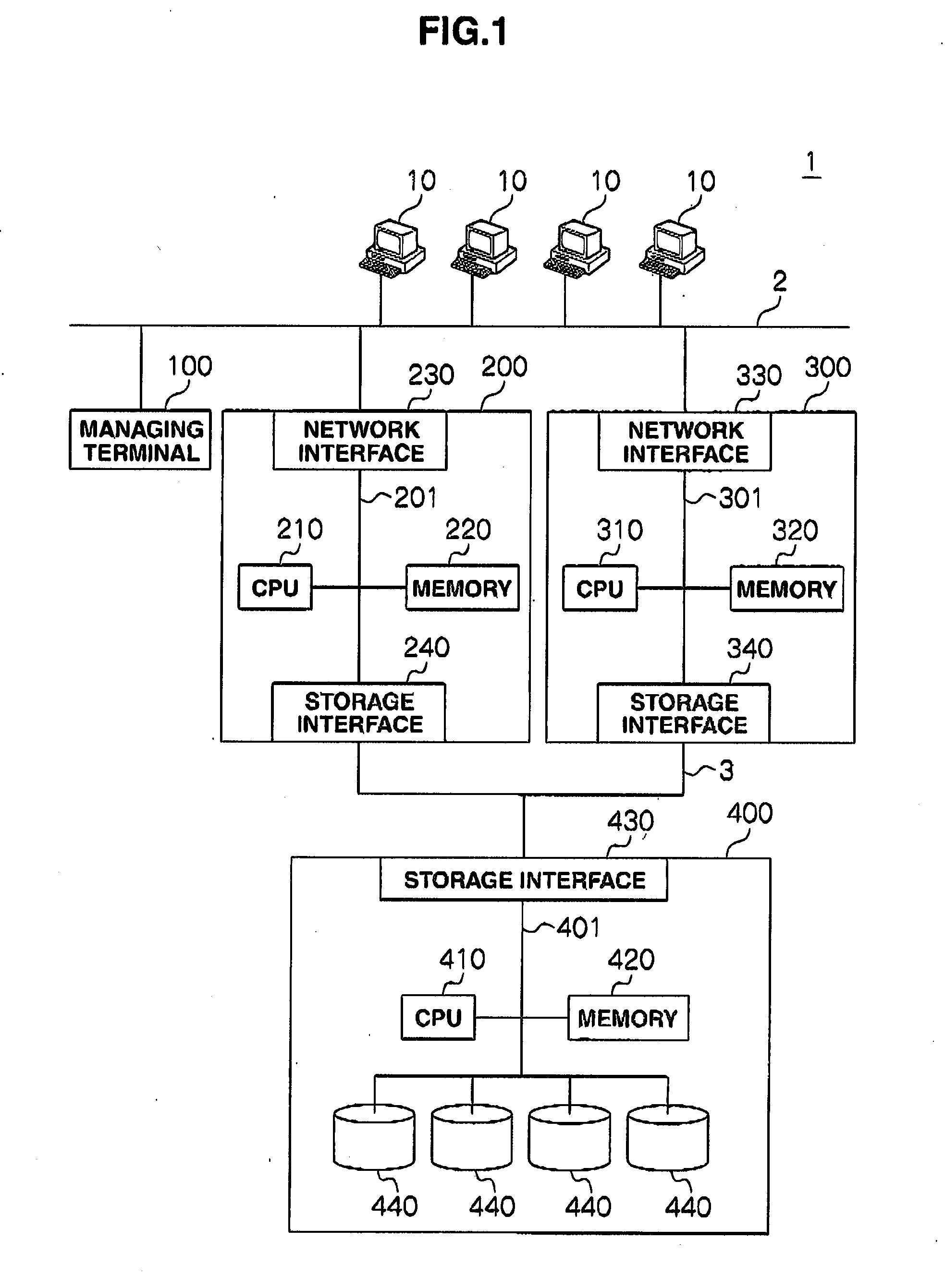
[0034]FIG. 1 is a block diagram illustrating a physical configuration of a storage system 1 to which the present invention is applied. As illustrated in FIG. 1, the storage system 1 includes a managing terminal 100, a plurality of NAS clients 10, two NAS servers 200 and 300, a storage apparatus 400. The plurality of NAS clients 10, the managing terminal 100, and the NAS servers 200 and 300 are connected through a network 2, and the NAS servers 200 and 300 and the storage apparatus 400 are connected through a network 3.

[0035]Meanwhile, while such a case will be described for a simple description that the storage system 1 includes the two NAS servers 200 and 300, the storage system 1 may be configured so as to include the three or more NAS servers. While such a case will be described that the storage system 1 includes one managing terminal 100, the storage system 1 may be configured so as to include a plurality of the managing terminals 100 managing each of the NAS servers 200 and 300...

second embodiment

[0112]Next, a second embodiment will be described. Meanwhile, since a physical configuration of a storage system of the second embodiment is the same as that of the storage system 1, the same codes as those of the storage system 1 are attached to the configuration of the storage system, and the illustration and the description will be omitted.

[0113]The second embodiment is configured so that, when writing data to a volume and reading data from the volume, the CPU 410 determines whether or not the virtual NAS identifier of the request source corresponds to the virtual NAS identifier of the LU storing information tables 900 stored in the volume, and when both virtual NAS identifiers correspond to each other, the CPU 410 writes data or reads data.

[0114]Thus, in the storage system 1 of the second embodiment, it is not possible to write data or read data to or from the virtual file server whose virtual NAS identifier does not correspond to the virtual NAS identifier of the LU storing inf...


PUM


Abstract

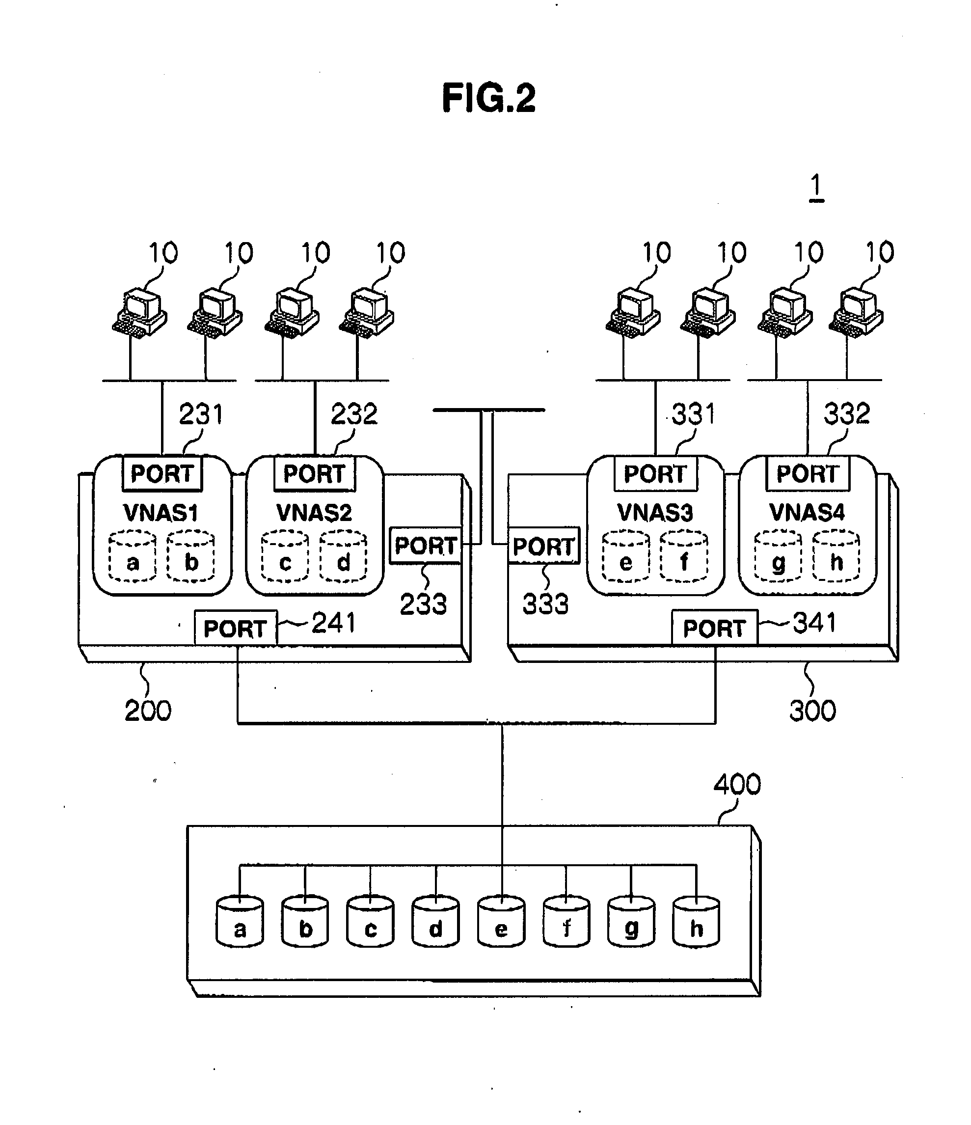
A time and an amount of data for setting information which is necessary to execute an exclusion process which is necessary when data is stored in a cluster system are reduced. A storage system included in the cluster system includes a plurality of volumes, and a plurality of virtual servers utilizing at least one or more volumes of the plurality of volumes for a data processing, each of the plurality of virtual servers can access all the plurality of volumes, and the volume utilized by the plurality of virtual servers to process data corresponds to the virtual servers.

Description

CROSS-REFERENCES TO RELATED APPLICATIONS[0001]This application relates to and claims priority from Japanese Patent Application No. 2008-082030, filed on Mar. 26, 2008, the entire disclosure of which is incorporated herein by reference.BACKGROUND[0002]1. Field of the Invention[0003]The present invention relates to a storage system and a volume managing method of the storage system, particularly, is preferable to be applied to the storage system and the volume managing method of the storage system which manage a volume in a cluster system operating a virtual server.[0004]2. Description of Related Art[0005]A cluster-base synchronization process is executed among nodes included in a cluster. Conventionally, it is necessary to synchronize databases among all the nodes included in the cluster when changing a setting of a service.[0006]That is, under such a cluster circumstance that a virtual file server function is used, it has been necessary to store setting information which is necessar...

Claims


Application Information

Patent Timeline
IPC IPC(8): G06F12/00G06F15/173G06F17/30
CPCG06F3/0611G06F3/067G06F3/0632
Inventor SUTOH, ATSUSHIKAMEI, HITOSHI
Owner HITACHI LTD
Learn More