Device for measuring the diffusion and/or absorption and/or refraction of a sample

Inactive Publication Date: 2009-10-08
KROHNE OPTOSENS
View PDF3 Cites 2 Cited by
  • Summary
  • Abstract
  • Description
  • Claims
  • Application Information

AI Technical Summary

Benefits of technology

[0011]On the one hand, it has been determined that it is not possible to strictly separate the specular reflexes that, on the one hand, are specularly reflected by the imaging element side interface of the protection element, and on the other hand, are specularly reflected by the sample side interface of the protection window, wherein the last-mentioned reflexes characterize the refraction of the sample. The overlapping of these reflexes caused by both interfaces of the protection element ranges differs in strength depending on whether or not the imaging element side interface has an antireflective coating or not.
[0012]On the other hand, it has been determined that the known devices are disadvantageous in the measuring of transparent samples with a mirror to the effect that the transmitted radiation is directed to the same area in which the specular reflexes of the sample side interface of the protection element are found. Thus, the transmitted radiation overlaps the target signal of the specular reflection in an interfering manner.
[0013]The above object is, firstly and essentially, met according to the invention with the device discussed here in that a refraction radiation source and a refraction receiver are arranged on the sensor side of the imaging element and arranged in regard to the imaging element so that the refraction radiation of the sample specularly reflected by the sample side interface of the protection element can essentially be received by the refraction receiver and the radiation specularly reflected by the imaging element side interface of the protection element essentially cannot be received by the refraction receiver. The arrangement of the refraction radiation source and the refraction receiver according to the invention ensures that refraction radiation of interest of the sample specularly reflected by the sample side interface of the protection element is not overlapped by the radiation specularly reflected by the imaging element side interface of the protection element, so that the refraction radiation of the sample can be selectively determined. When speaking of a “refraction radiation source” and a “refraction receiver,” then, in this context it is meant that this radiation source and the receiver assigned to this radiation source are intended to determine the refraction radiation of the sample, however, it does not mean that th

Problems solved by technology

On the one hand, it has been determined that it is not possible to strictly separate the specular reflexes that, on the one hand, are specularly reflected by the imaging element side interface of the protection element, and on the other hand, are specularly reflected by the sample side interface of the protection window, wherein the last-mentioned reflexes characterize the refraction of the sample.
On the ot

Method used


Image

  • Device for measuring the diffusion and/or absorption and/or refraction of a sample
  • Device for measuring the diffusion and/or absorption and/or refraction of a sample
  • Device for measuring the diffusion and/or absorption and/or refraction of a sample

Examples


Example

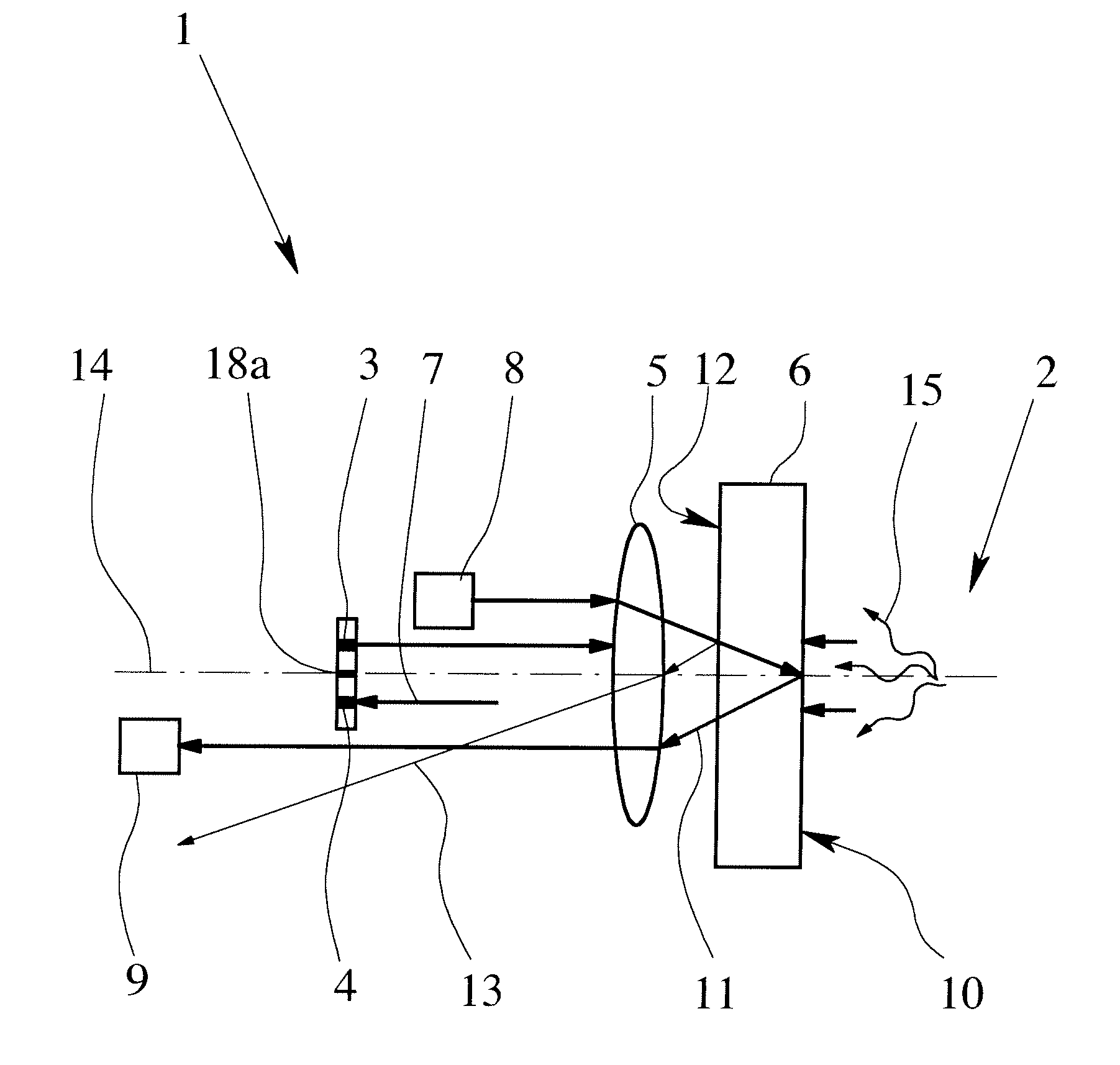
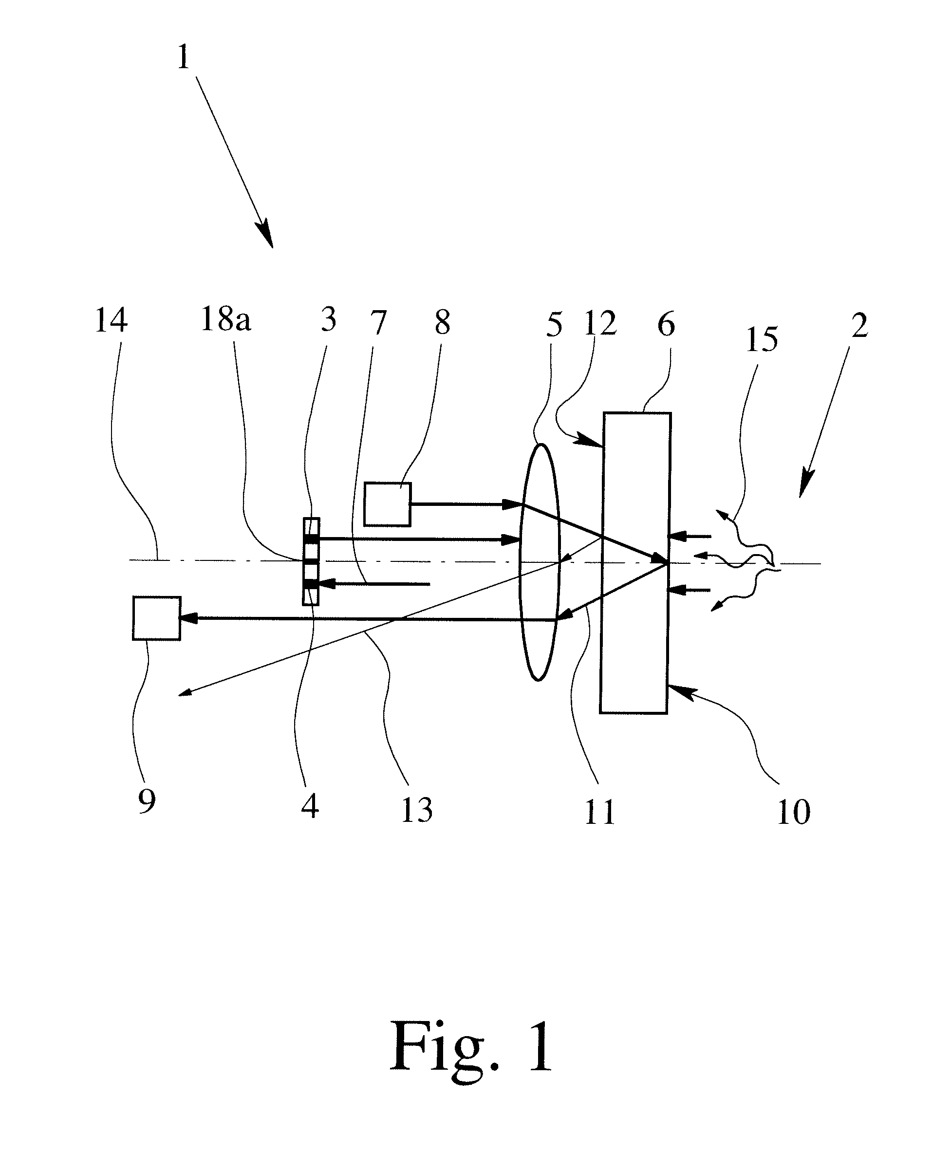
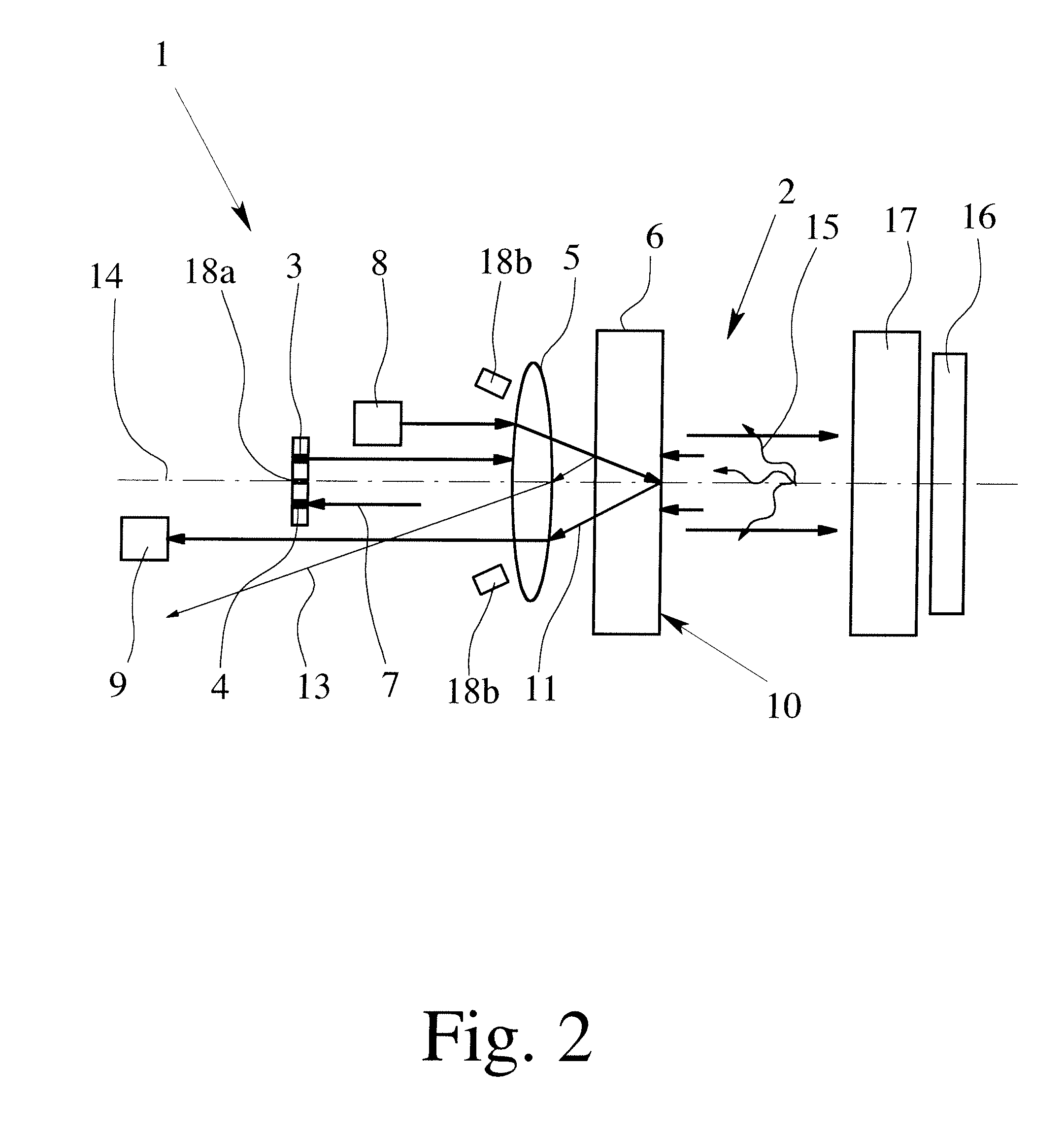
[0022]FIGS. 1 & 2 each show an embodiment of a measuring device 1 according to the invention for measuring the diffusion and / or absorption and / or refraction of a sample 2. The device 1 has a radiation source 3, a receiving element 4 an optical imaging element 5 in the form of a lens and a protection element 6. The radiation source 3 and the receiving element 4 are arranged on the sensor side of the optical imaging element 5 and the protection element 6 is arranged on the sample side of the imaging element 5 and neighbors the imaging element 5. The protection element 6 protects the device 1 from the sample 2 penetrating into the sensor side of the device 1, i.e., in the part of the device that also includes the radiation source 3, the receiving element 4 and the optical imaging element 5. The radiation source 3, the imaging device 5 and the receiving element 4 are collectively arranged so that transmitted sample radiation 7 can be received by the receiving element 4.

[0023]Furthermore...


PUM


Abstract

Device for measuring at least one of diffusion, absorption and refraction of a sample, having a radiation source, at least one receiving element, an optical imaging element and a protection element, the radiation source and the receiving element being arranged on the sensor side of the optical imaging element, the protection element being arranged on the sample side of the imaging element and adjacent to the imaging element and the radiation source. A refraction radiation source and a refraction receiver are arranged on the sensor side of the imaging element and arranged relative to the imaging element so that the refraction radiation of the sample specularly reflected by the sample side interface of the protection element can essentially be received by the refraction receiver and the radiation specularly reflected by the imaging element side interface of the protection element essentially cannot be received by the refraction receiver.

Description

BACKGROUND OF THE INVENTION[0001]1. Field of Invention[0002]The invention relates to a device for measuring the diffusion and / or absorption and / or refraction of a sample, having a radiation source, at least one receiving element, an optical imaging element and a protection element, wherein the radiation source and the receiving element are arranged on the sensor side of the optical imaging element, wherein the protection element is arranged on the sample side of the imaging element and adjacent to the imaging element, and wherein the radiation source, the imaging element and the receiving element are collectively arranged so that directly transmitted and / or specularly reflected sample radiation can be received by the receiving element.[0003]2. Description of Related Art[0004]Measuring devices of the type mentioned above have been known for quite some time and are used in the fields of chemical analysis and environmental, quality and process control. Such devices are known as encapsu...

Claims


Application Information

Patent Timeline
IPC IPC(8): G01N21/00G01N21/41G01N21/47
CPCG01N21/55
Inventor MITTENZWEY, KLAUS-HENRIKSINN, GERT
Owner KROHNE OPTOSENS
Why Eureka
Try Eureka