Lock mechanism, slide apparatus, and mobile handset apparatus

Inactive Publication Date: 2009-10-08
SNAPTRACK
View PDF5 Cites 27 Cited by
  • Summary
  • Abstract
  • Description
  • Claims
  • Application Information

AI Technical Summary

Benefits of technology

[0018]According to an embodiment of the present invention, a lock mechanism and a click mechanism are provided in an integrated manner and not as independent component parts. As a result, the number of component parts can be reduced in an apparatus to which an embodiment of the present i

Problems solved by technology

As a result of the above, the device becomes more complex.
Furthermore, if the user-operated portion of the lock mechanism is enlarged to impro

Method used


Image

  • Lock mechanism, slide apparatus, and mobile handset apparatus
  • Lock mechanism, slide apparatus, and mobile handset apparatus
  • Lock mechanism, slide apparatus, and mobile handset apparatus

Examples


Example

[0051]Hereinafter, preferred embodiments of the present invention will be described in detail and with reference to the accompanying drawings.

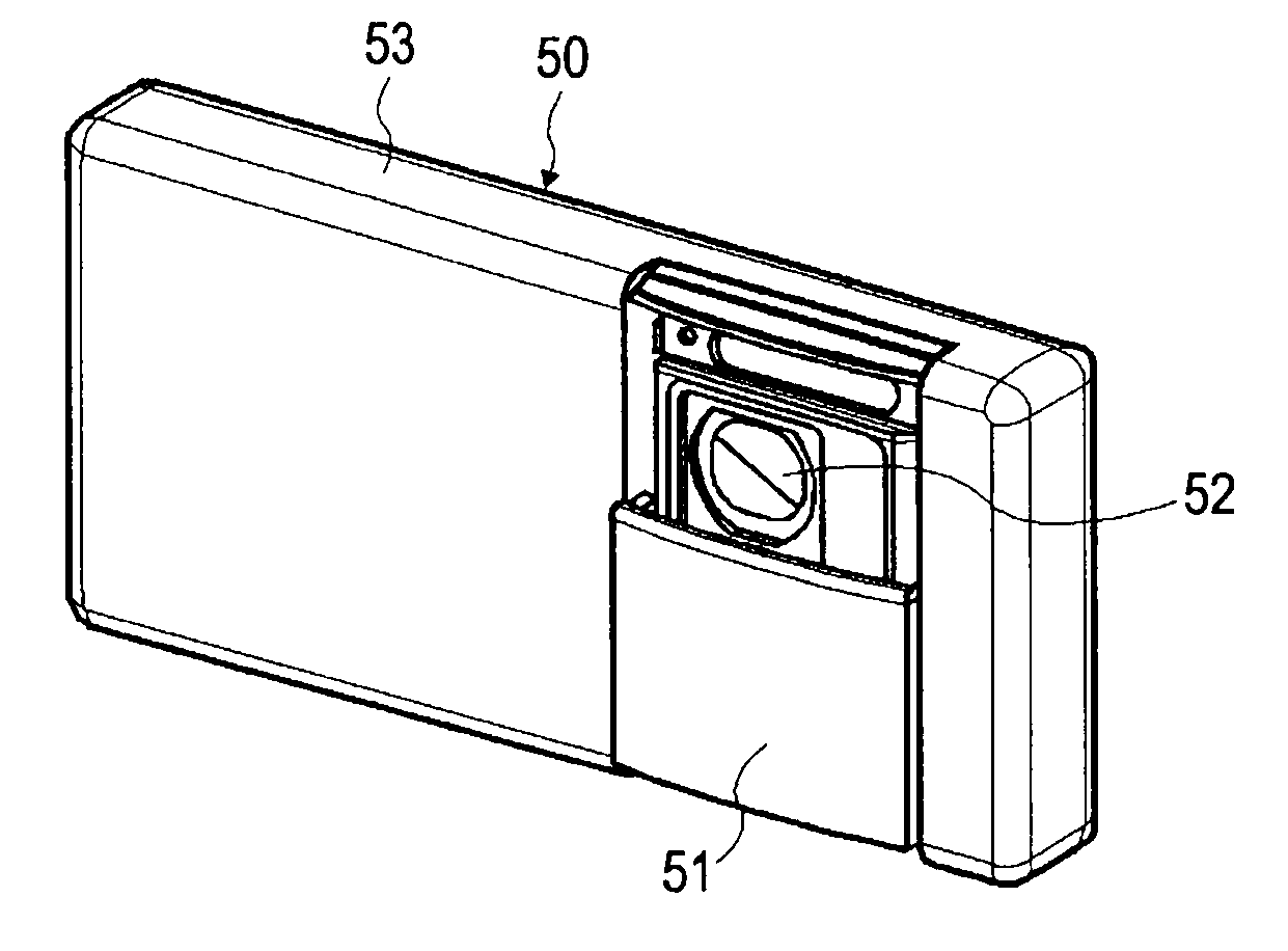
[0052]FIGS. 5A to 5D are external views of a mobile device 50 provided with a camera unit having a cover that can be opened and closed, and configured in accordance with an embodiment of the slide apparatus of the present invention. FIG. 5A is a left-side view showing the closed cover state wherein the camera unit 52 is closed and covered by the cover 51. FIG. 5B is a front view showing the closed cover state wherein the camera unit 52 is closed and covered by the cover 51. FIG. 5C is a left-side view showing the open cover state. FIG. 5D is a front view showing the open cover state. As long as an external force is not at work, the cover 51 is maintained in the closed state due to the urging force of an elastic member or similar urging means provided inside the device. When the user places his or her hand on the top edge or the front surface o...


PUM


Abstract

A lock mechanism for a sliding object includes a slide arm, a rotating lever, and urging means. When an external pressing force presses the slide arm member in opposition to an urging force imparted by the urging means, the slide arm member is moved along a slide path, thereby causing the rotating lever member to rotate. When the slide arm member is pressed further, the tip of the rotating lever member rides onto and is stopped against the lateral surface of the slide arm member, such that the slide arm member and the rotating lever member remain stopped at the current position even if the pressing force is released.

Description

BACKGROUND OF THE INVENTION[0001]1. Field of the Invention[0002]The present invention relates to a slide apparatus and mobile handset having a sliding object that slides along a predetermined slide path, wherein the sliding object is stably held at two points on the slide path. More particularly, the present invention relates to a lock mechanism for realizing a function like the above.[0003]2. Description of the Related Art[0004]FIG. 1 illustrates a schematic configuration of a mobile phone or similar mobile device provided with a camera unit 12 housed in a chassis 13, as well as a cover 11 (the sliding object herein) that selectively covers the lens unit of the camera unit 12 in order to protect the lens unit. When the camera of the mobile device is not in use, the camera unit 12 is closed and covered by the cover 11, as shown in FIG. 1A. The cover 11 is slidably supported by the chassis 13, such that when the user applies an external force F1 to the cover 11, the cover 11 is moved...

Claims


Application Information

Patent Timeline
IPC IPC(8): G03B17/00E05C1/08E05C5/02
CPCH04M1/0237Y10T70/5173Y10T292/0961Y10T292/0863Y10T292/096
Inventor MATSUMOTO, MASAO
Owner SNAPTRACK
Why Eureka
Try Eureka