Clip

Active Publication Date: 2009-10-08
PIOLAX CO LTD
View PDF12 Cites 14 Cited by
  • Summary
  • Abstract
  • Description
  • Claims
  • Application Information

AI Technical Summary

Benefits of technology

[0026]According to the above aspects of the present invention, the upper end portions of the elastic locking members are gradually reduced in width and connected to the lower surface of the head portion. Therefore, when an external force is exerted on the elastic locking members, not only are the elastic locking members deflected inwardly, but the elastic locking members tend to be twisted at their narrowed upper end portions, so that the elastic locking members can be deflected in conformity with the inner periphery of the mounting hole, making it possible to maintain the requisite engagement force with respect to the mounting hole.
[0027]According to the clip of the present invention, even when the position of the mounting hole is deviated due to inter-component dimensional deviation, and the locking leg has to be inserted obliqu

Problems solved by technology

Hei 4-105615, the leg portion includes four legs (elastic locking members) independently extending from the head portion, so no shaft portion exists at the center of the elastic locking members, and when the position of the mounting hole is deviated due to dimensional deviation between components, and the leg portion has to be obliquely inserted into the mounting hole, buckling may be caused to make the insertion impossible or breakage may be caused.
However, when there is a considerable dimensional deviation between the mounting holes, and the leg portion has to be inserted into the mounting hole obliquely at a considerably large angle with respect thereto, the insertion is effected with the protrusions being scraped by the inner periphery of the moun

Method used


Image

  • Clip
  • Clip
  • Clip

Examples


Embodiment Construction

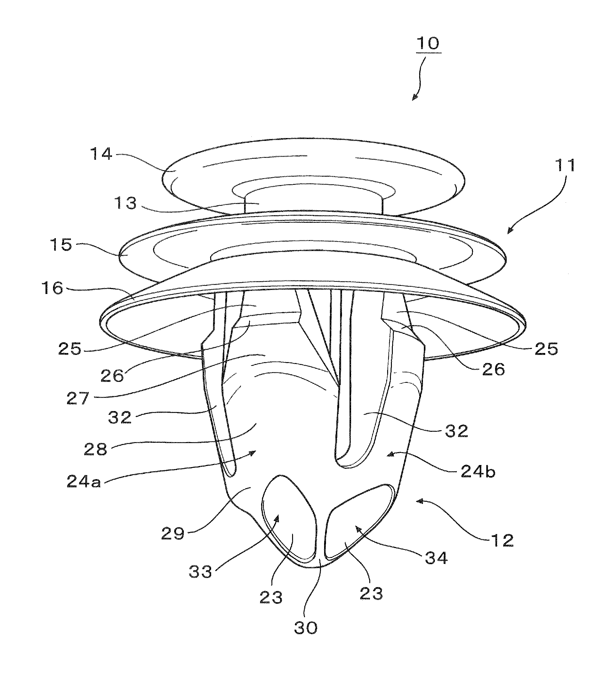
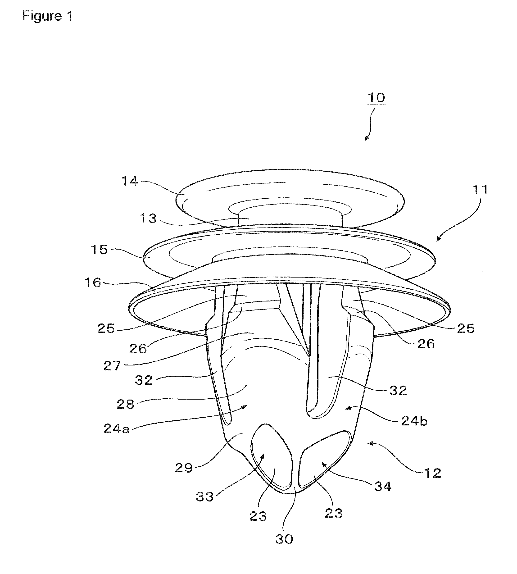
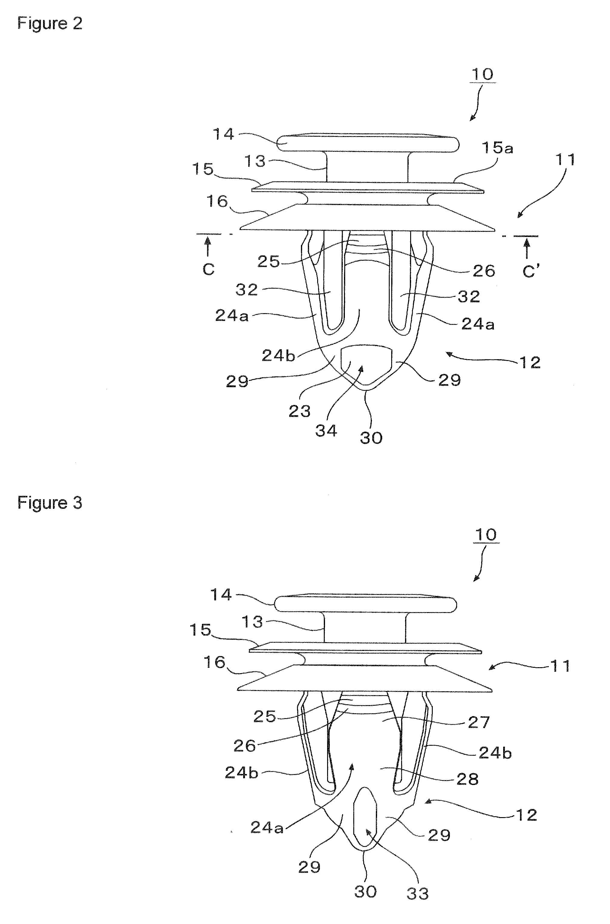
[0045]Next, a clip according to an embodiment of the present invention will be described with reference to FIGS. 1 through 14. FIG. 1 is a perspective view of the clip; FIG. 2 is a front view of the clip; FIG. 3 is a right-hand side view of the clip (which is the same as a left-hand side view thereof); FIG. 4 is a plan view of the clip (which is the same as a rear view thereof); FIG. 5 is a bottom view of the clip; FIG. 6 is a sectional view taken along the arrow line A-A′ of FIG. 4; FIG. 7 is a sectional view taken along the arrow line B-B′ of FIG. 4; FIG. 8 is a sectional view taken along the arrow line C-C′ of FIG. 2; FIG. 9 is an explanatory view showing a locking leg of the clip in sections as taken at various heights; FIG. 10 is an explanatory view of a mold for producing the clip; FIG. 11 is a sectional view showing how a mounting member is fixed to a mounting hole of a mounting panel by using the clip; FIG. 12 is a sectional view illustrating how the clip is deflected when i...


PUM


Abstract

Provided is a clip whose locking leg can be inserted and locked without being buckled even when the position of a mounting hole is deviated and which provides a substantially uniform deflection rigidity over the entire periphery even when a lateral external force is applied to the locking leg in the mounted state. A clip (10) has a head portion (11) and a locking leg (12), and the locking leg (12) includes a shaft portion (21) vertically extending from the head portion (11) and a plurality of elastic locking legs (24a and 24b) which are arranged at given intervals in the outer periphery of the shaft portion (21), which have their upper ends connected to the lower surface of the head portion (11), and each of which has two portions on both sides of a lower end connected to connection ribs (23) extending from the shaft portion (21); the outer periphery of the shaft portion (21) excepting the connection ribs (23) is situated on an inner side of a inner periphery of the elastic locking members (24a and 24b); such that the locking leg (12) can pass through a mounting hole (20) of a panel (19) without coming into contact at the inner periphery of the elastic locking members (24a and 24b) with the outer periphery of the shaft portion (21).

Description

BACKGROUND OF THE INVENTION[0001]1. Field of the Invention[0002]The present invention relates to a clip used to fix a component, such as an automotive interior component, to a mounting hole of a vehicle body panel or the like.[0003]2. Description of the Related Art[0004]Conventionally, as a clip of this type, there has been used one having a head portion to be fixed to a component and a locking leg extending from the head portion, with the locking leg being inserted into a mounting hole of a vehicle body panel or the like for fixation.[0005]For example, Japanese Utility Model Application Laid-Open No. Hei 4-105615 discloses a clip which is equipped with a head portion and a leg portion and whose leg portion is to be inserted into a hole of a panel of a vehicle body or the like to be thereby locked thereto, the leg portion including four legs independently extending from the head portion, each leg being integrally molded so as to have an intermediate portion expanding radially outwar...

Claims


Application Information

Patent Timeline
IPC IPC(8): F16B19/00
CPCY10T24/309F16B21/086
Inventor NAKAZATO, HIROSHI
Owner PIOLAX CO LTD
Why Eureka
Try Eureka