Rendering of Subsurface Scattering Effects in Translucent Objects

a technology of subsurface scattering and translucent objects, applied in the field of electronic rendering of images and movies, can solve the problems of inability to realize inability to achieve the effect of lighting,

Active Publication Date: 2009-10-08
DREAMWORKS ANIMATION LLC
View PDF3 Cites 21 Cited by
  • Summary
  • Abstract
  • Description
  • Claims
  • Application Information

AI Technical Summary

Problems solved by technology

A major impediment to reaching this goal is the inherent computational limitations of existing computer systems.
More specifically, lighting continues to pose challenges in the field of computer graphics.
Unfortunately, for most situations, such a system would be impractical as it would require a very large amount of computing resources.
Considering the incredibly large number of photons illuminating a scene, and the complex paths each photon may take when being reflected of various objects in a scene, this is not practical.
While using a direct light system significantly reduces computational costs, these systems may, in certain situations, create images that are very unrealistic.
For example, dire...

Method used


Image

  • Rendering of Subsurface Scattering Effects in Translucent Objects
  • Rendering of Subsurface Scattering Effects in Translucent Objects
  • Rendering of Subsurface Scattering Effects in Translucent Objects

Examples


Embodiment Construction

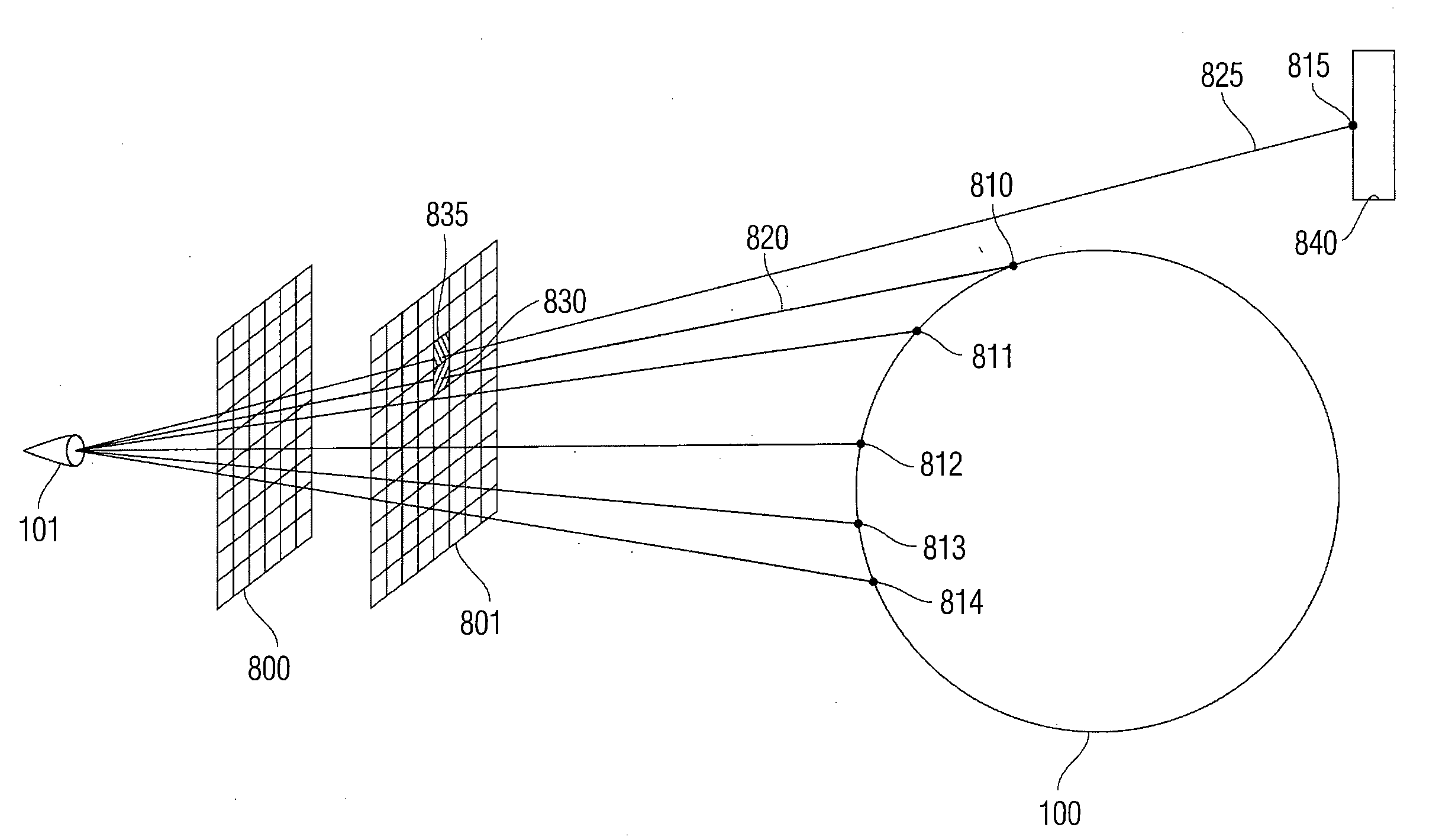
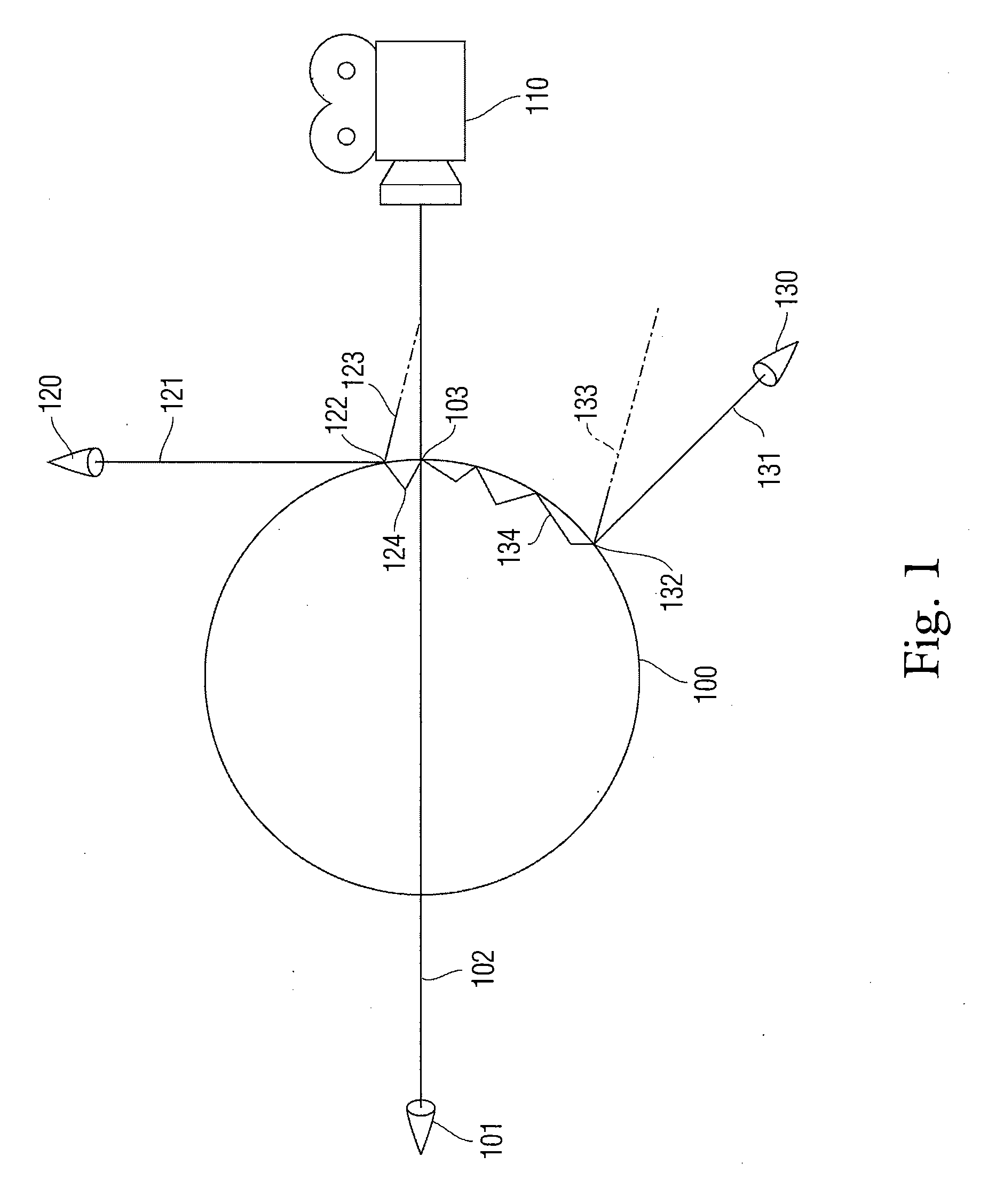
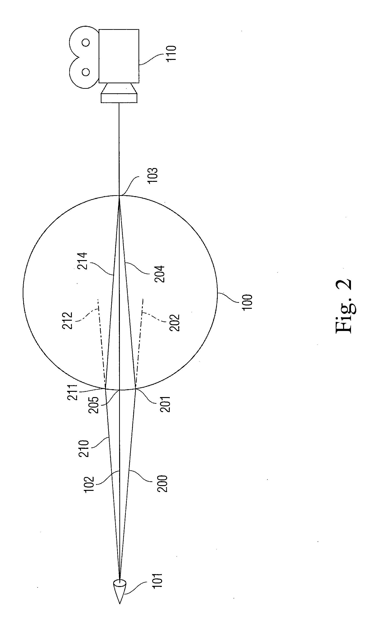
[0026]In the following description of preferred embodiments, reference is made to the accompanying drawings which form a part hereof, and in which it is shown by way of illustration specific embodiments in which the invention may be practiced. It is to be understood that other embodiments may be utilized and structural changes may be made without departing from the scope of the preferred embodiments of the present invention.

[0027]In the following description, a “ray of light” is an abstraction used for computational purposes. It signifies a line in space through which light travels, and need not be associated with a single photon. The number of rays of light emitted by a single light source may vary and depend on the desired resolution of the scene. However, this number is usually much smaller than the number of actual photons emitted by a real source of light.

[0028]Embodiments of the present invention are directed to modifying an existing scheme for providing translucent illuminati...


PUM


Abstract

Embodiments are directed to modifying an existing scheme for providing translucent illumination in order to take account of subsurface scattering. The color of a selected point of a translucent object can be determined using existing methods. The existing methods need not take subsurface scattering into account. Then, a contribution to the color at the selected point due to subsurface scattering may be calculated. The contribution due to subsurface scattering may be calculated based on a photon map. Embodiments of the invention also include the use of different types of photon maps. In some embodiments, a standard photon map may be used. In other embodiments, a photon map may be defined in a manner similar to a depth map. Thus, the entries of a photon map may be defined in terms of an angle from a light source and a distance between an object's surface and a light source.

Description

BACKGROUND[0001]1. Field[0002]This application relates to the electronic rendering of images and movies in general and more specifically to the shading of translucent objects.[0003]2. Related Art[0004]Computer graphics are used in various fields, such as animation, computer games, etc. An important goal of computer graphics is the ability to generate virtual images that are realistic and / or esthetic. A major impediment to reaching this goal is the inherent computational limitations of existing computer systems.[0005]More specifically, lighting continues to pose challenges in the field of computer graphics. Naturally, light is an important factor in how one perceives an image. An observer (e.g., a human eye or a camera) perceives an object by detecting light reflected from that object. In other cases, the light may be passing (or transmitted) through the object or be refracted by the object instead. The light detected from an object may be classified in two types. Direct light is lig...

Claims


Application Information

Patent Timeline
IPC IPC(8): G01J3/46G06T15/50
CPCG06T2210/62G06T15/50
Inventor TARTAGLIA, BRUCE NUNZIOPOWELL, ALEXANDER P.
Owner DREAMWORKS ANIMATION LLC
Why Eureka
Try Eureka