
Serrated knife

a serrated knife and blade technology, applied in the field of serrated knives, can solve the problems of small boat operators often encountering problems, blades are particularly ineffective, and the serrated cutting device has not proved particularly useful in industrial applications

Inactive Publication Date: 2009-10-15
DIAZ SCOTT DOUGLAS
View PDF17 Cites 7 Cited by
  • Summary
  • Abstract
  • Description
  • Claims
  • Application Information

AI Technical Summary

Benefits of technology

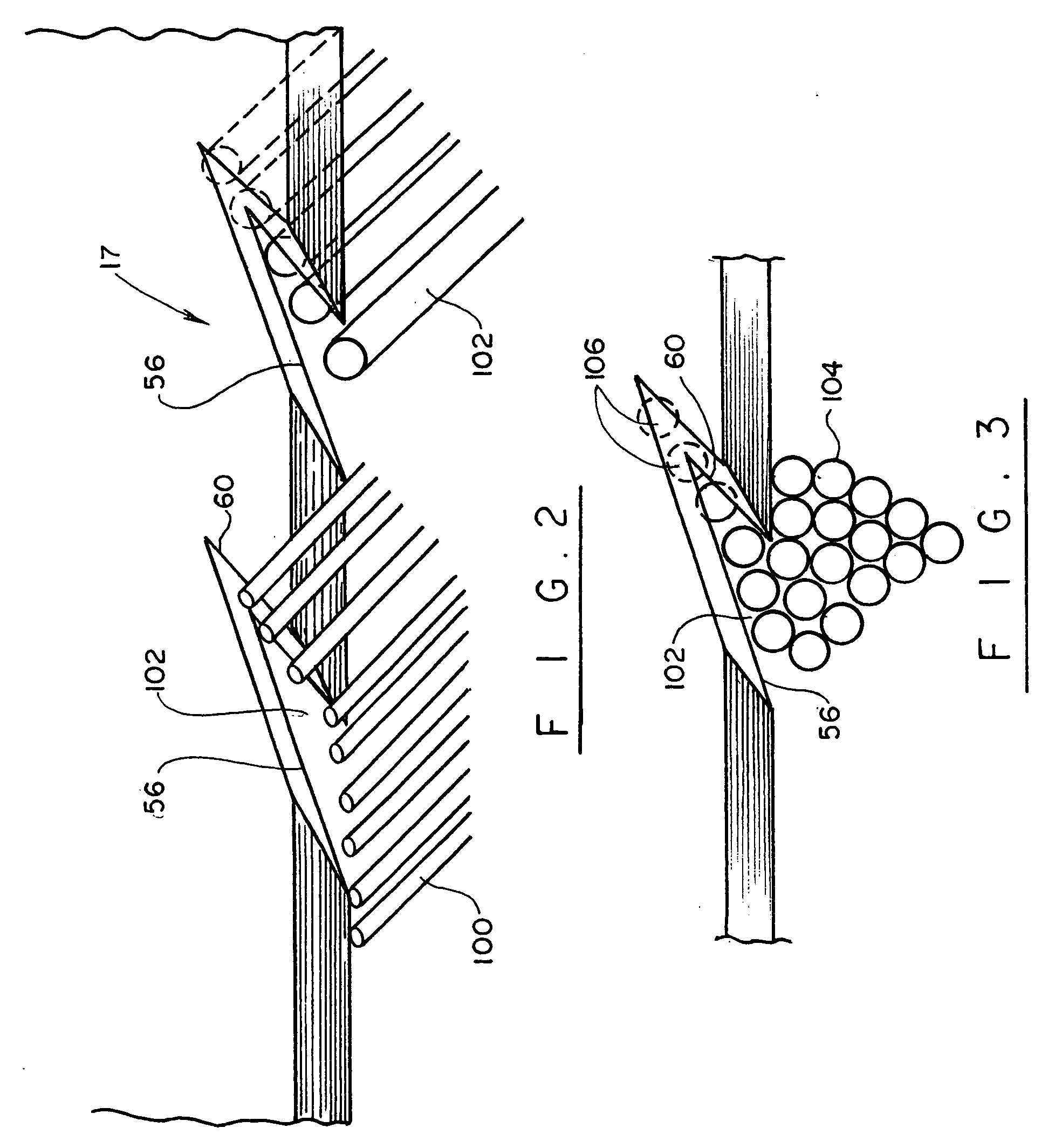
[0008]It is another object of the present invention to provide a serrated cutting blade that can be used for cutting ropes and similar objects in an accurate and efficient manner, with minimal fraying of the rope.

Problems solved by technology

However, other than such saw blades, serrated cutting devices have not proved particularly useful in industrial applications such as, for example, hand cutting of ropes, bundles of twine, and the like.
Such blades are particularly ineffective when a user needs to cut through a thick rope.
Small boat operators often encounter a problem when a rope becomes entangled on a propeller or a shaft of a marine vessel and divers have to be called to free the propeller from the shaft to return the vessel to operation.
While current state-of-art utility knives using single-edge cutting blades are functional in many circumstances, they dull quickly when applied for the cutting of a multi-strand rope, resulting in cutting operations that are laborious and time consuming.
The job of cutting a rope under water is even more difficult.

Method used


Image

  • Serrated knife
  • Serrated knife
  • Serrated knife

Examples


Embodiment Construction

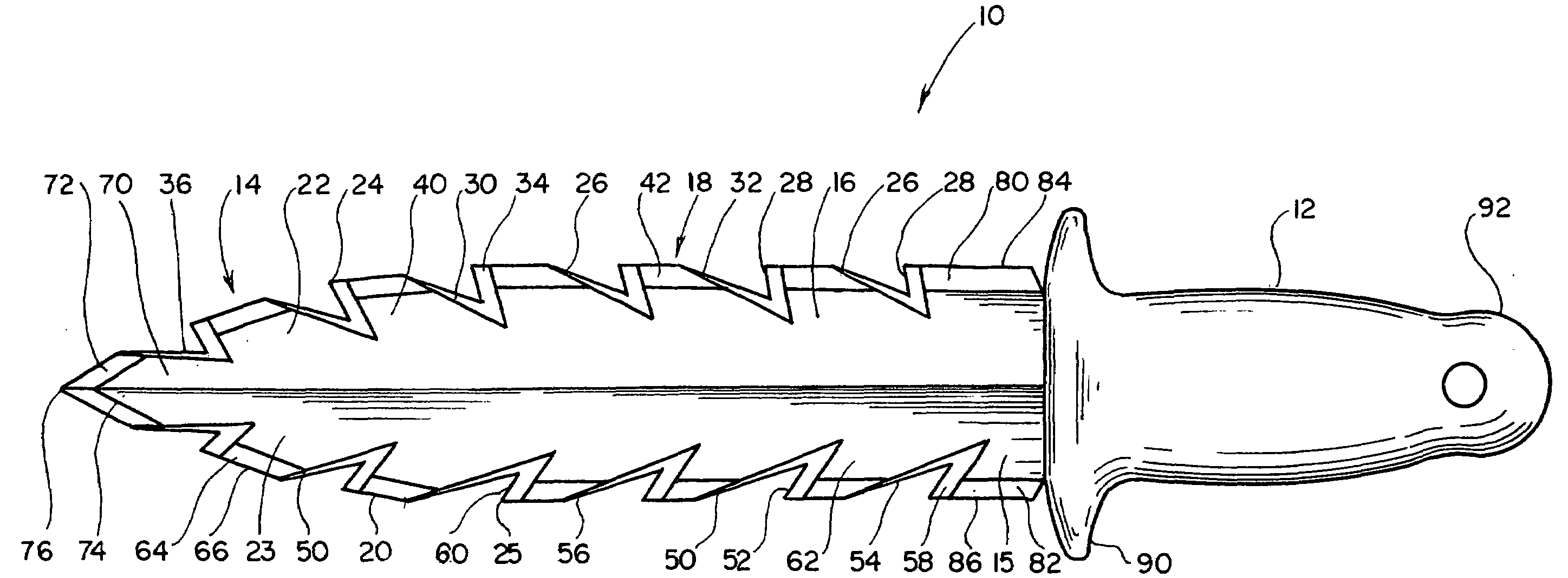
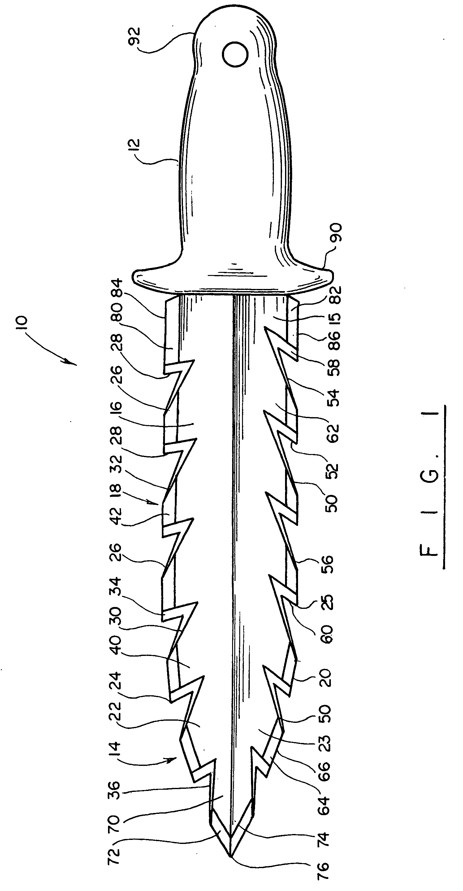
[0014]Turning now to the drawings in more detail, numeral designates a knife in accordance with the present invention. The knife 10 comprises a handle 12 and a blade 14 secured to the handle 12 at a proximate end 15. The blade 14 comprises a front, 16, a back 17, which is a mirror image of the front 16, a first edge 18 and a second edge 20.

[0015]The first edge 18 and the second edge 20 each comprise a plurality of sharpened teeth 22, 23, respectively, each of the teeth 22 having a distal end 24 extending away from a central longitudinal axis, or centerline X of the blade 14. A line connecting each of the distal ends 24 actually defines the first edge 18. Each of the teeth 23 has a distal end 25, which extends away from the central axis X of the blade 14. A line connecting each of the distal ends 25 defines the second edge 20.

[0016]Each of the teeth 22 comprises a first serration side 26 and a second serration side 28. The first serration side 26 comprises a pair of beveled surfaces ...


PUM

PropertyMeasurementUnit
angleaaaaaaaaaa
angleaaaaaaaaaa
angleaaaaaaaaaa

Abstract

A knife has a cutting blade with an elongate planar body having a front and a back, a first and second opposite edges, the elongate body having a centerline extending between the first and the second edges, each of said first and second edges being provided with a plurality of angularly-oriented notches defined by beveled surfaces, which intersect to form cutting edges. The notches have a generally V-shaped configuration and have one or more sides that extend at an acute angle in relation to the centerline.

Description

BACKGROUND OF THE INVENTION[0001]This invention relates to knives, and more particularly to utility knives that are used for cutting high density materials, such as ropes, cables and the like.[0002]Knives with serrated cutting edges are old and well-known in the prior art. The serrated blades are conventionally used in household tools, such as table knives and meat cutting knives and a wide variety of saw blades, straight, circular, and band.[0003]However, other than such saw blades, serrated cutting devices have not proved particularly useful in industrial applications such as, for example, hand cutting of ropes, bundles of twine, and the like. Most often, the cutting implement is in a form of a single edge blade that has a sharp edge formed along one edge, while the other edge is dull to protect the user's hand. Such blades are particularly ineffective when a user needs to cut through a thick rope. Small boat operators often encounter a problem when a rope becomes entangled on a p...

Claims


Application Information

Patent Timeline
Patent Type & Authority Applications(United States)
IPC IPC(8): B26B9/02
CPCB26B9/02B26B3/00Y10T83/04
Inventor DIAZ, SCOTT DOUGLAS
Owner DIAZ SCOTT DOUGLAS
Learn More