Impact screwdriver

a screwdriver and impact technology, applied in the field of impact screwdrivers, can solve the problems of boss falling back or getting stuck, still has some drawbacks,

Inactive Publication Date: 2009-10-15
HSIEH CHIH CHING
View PDF3 Cites 9 Cited by
  • Summary
  • Abstract
  • Description
  • Claims
  • Application Information

AI Technical Summary

Benefits of technology

[0005]The main objective of the present invention is to provide an improved impact screwdriver that further drives a screw when being longitudinally impacted.

Problems solved by technology

However, it still has some drawbacks.
First, the boss must overcomes the top of the V-shaped slot to rotate the shank and move downward continually, if a impact power is not enough to overcome the top of the V-shaped slot, the boss will fall back or get stuck, wherein the shank is rotated back and unfastens the screw.

Method used


Image

  • Impact screwdriver
  • Impact screwdriver
  • Impact screwdriver

Examples


Embodiment Construction

[0018]In order that those skilled in the art can further understand the present invention, a description will be provided in details below. However, these descriptions and the appended drawings are only used for those skilled in the art to understand the objects, features, and characteristics of the present invention, but not to be used to confine the scope and spirit of the present invention defined in the appended claims.

[0019]Referring the first embodiment of FIG. 1 to FIG. 6, a first embodiment of an impact screwdriver in accordance with the present invention is illustrated.

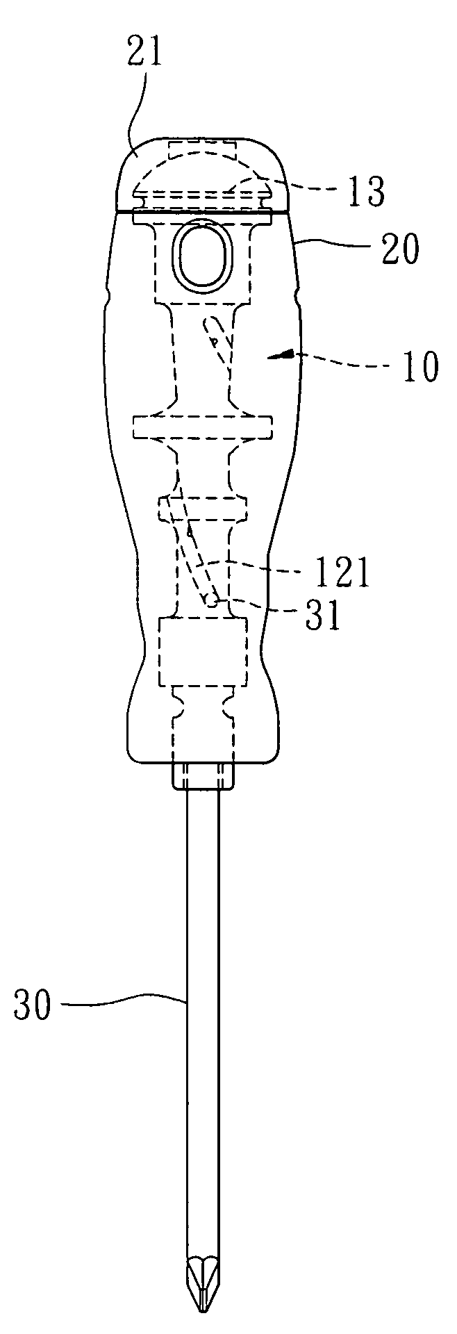
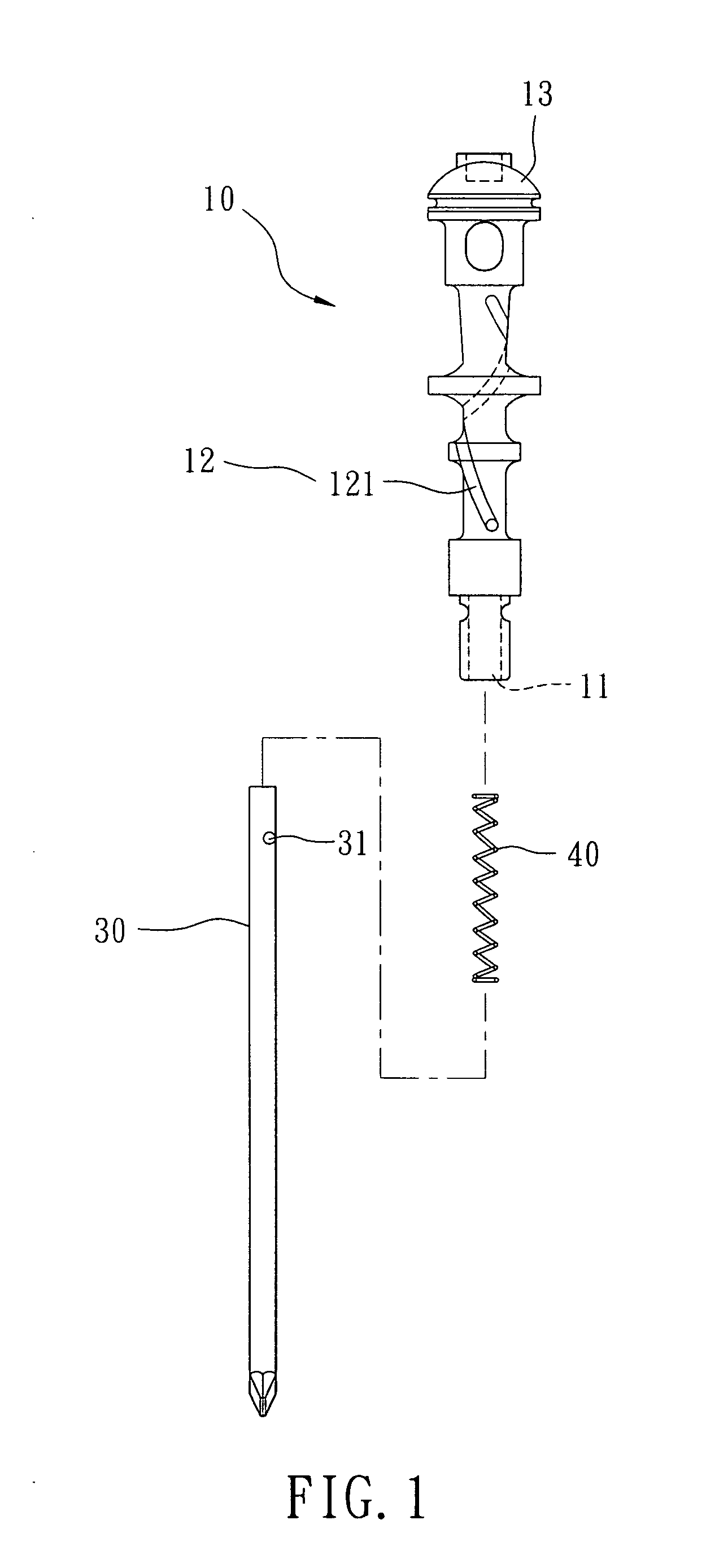
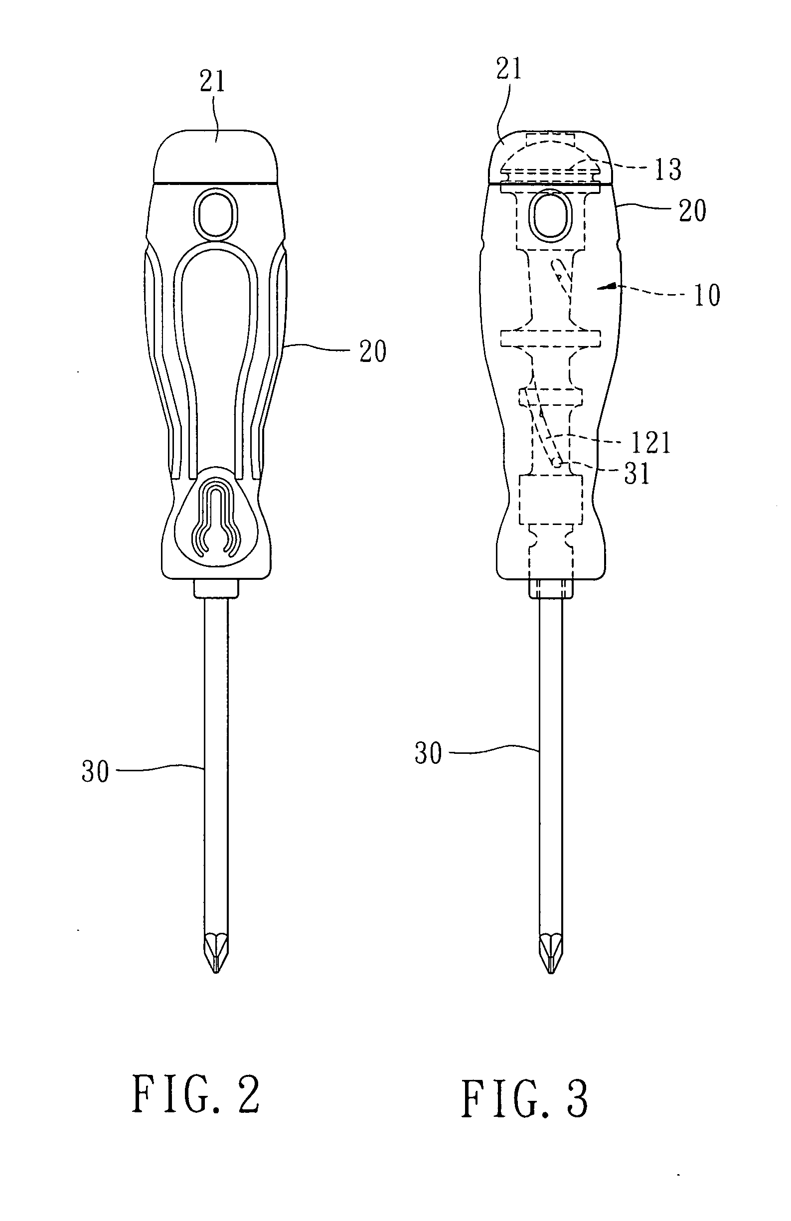
[0020]In the embodiment, the impact screwdriver comprises a handle 20 formed by injection molding. A spindle 10 is mounted in the handle 20 and has a first end and a second end extending to an outer surface of the handle 20. A percussion portion 13 is longitudinally mounted on the first end of the spindle 10 for loading impact. A high hardness percussion block 21 (e.g. steel) is mounted on the handle 20 and c...


PUM


Abstract

An impact screwdriver includes: a handle has a spindle mounted therein. The spindle has a first end and a second end extending to an outer surface of the handle, a percussion portion is mounted on the first end of the spindle for loading impact, a tank is axially defined in the spindle from the second end of the spindle, a guiding structure is defined in an inner periphery of the tank, an elastic member and a driving shank is sequentially mounted in the tank for cooperating each other, a boss is positioned on the driving shank and installed into the guiding structure to make the guiding structure drive the driving shank when the percussion portion is impacted.

Description

FIELD OF THE INVENTION[0001]The present invention relates to an impact screwdriver, and more particularly to an impact screwdriver that further drives a screw when being longitudinally impacted.BACKGROUND OF THE INVENTION[0002]Referring to U.S. Pat. No. 6,860,180, “Screwdriver provided with percussion mechanism to facilitate the unfastening and the fastening of screw” is disclosed. In that a screwdriver comprises a handle and a shank. The handle is provided at a head end of the handle with a percussion block. The shank is put through the interior of the handle such that one end of the shank is fastened with the percussion block, and the other end of the shank extends out of the other end of the handle. The shank is provided on the other end thereof with a percussion-rotation mechanism which is in turn fastened with a tip. The mechanism enables the tip to turn instantaneously at the time when the percussion block is impacted.[0003]Above mentioned structure provides a V-shaped slot fo...

Claims


Application Information

Patent Timeline
Patent Type & Authority Applications(United States)
IPC IPC(8): B25B23/02
CPCB25B19/00
Inventor HSIEH, CHIH-CHING
Owner HSIEH CHIH CHING
Why Eureka
Try Eureka