
External heating type reduced pressure fryer

Inactive Publication Date: 2009-10-15
TAKAHASHI KAZUO
View PDF1 Cites 8 Cited by
  • Summary
  • Abstract
  • Description
  • Claims
  • Application Information

AI Technical Summary

Benefits of technology

[0013]According to the reduced pressure fryer of the invention, even when a large amount of water included in the food or water adhered thereto is mixed to the oil in the frying tank in subjecting the food to the frying treatment, the water is interrupted by the first baffle plate when the oil in the frying tank is transferred to the heating apparatus by detouring the first baffle plate installed at the oil / water separating portion to promote evaporation to the gas phase portion by boiling, and therefore, cavitation is not brought about by sucking steam to the circulating pump, as a result, even when the frying treatment of the food is carried out in the frying tank, a cycle of heating and circulating the oil can be carried out between the frying tank and the heating apparatus, the reduced pressure fryer is excellent in a driving efficiency and also a temperature control thereof is facilitated.

Problems solved by technology

The reason is that at inside of the main tank, when the frying treatment is carried out, a large amount of water included in food or water adhered thereto is mixed in the oil, and therefore, when the water is sucked to the frying pump, there is a concern of bringing about a cavitation.
However, according to the method of intermittently carrying out the heating and circulating circle as described above, during a time period of carrying out the cycle of heating and circulating the oil, the treatment of frying food is interrupted, and therefore, an operating efficiency is deteriorated, further, during the frying treatment, the oil the temperature of which is reduced cannot be heated, and therefore, a temperature control becomes unstable and it is difficult to provide a product of a constant quality.

Method used


Image

  • External heating type reduced pressure fryer
  • External heating type reduced pressure fryer
  • External heating type reduced pressure fryer

Examples


first embodiment

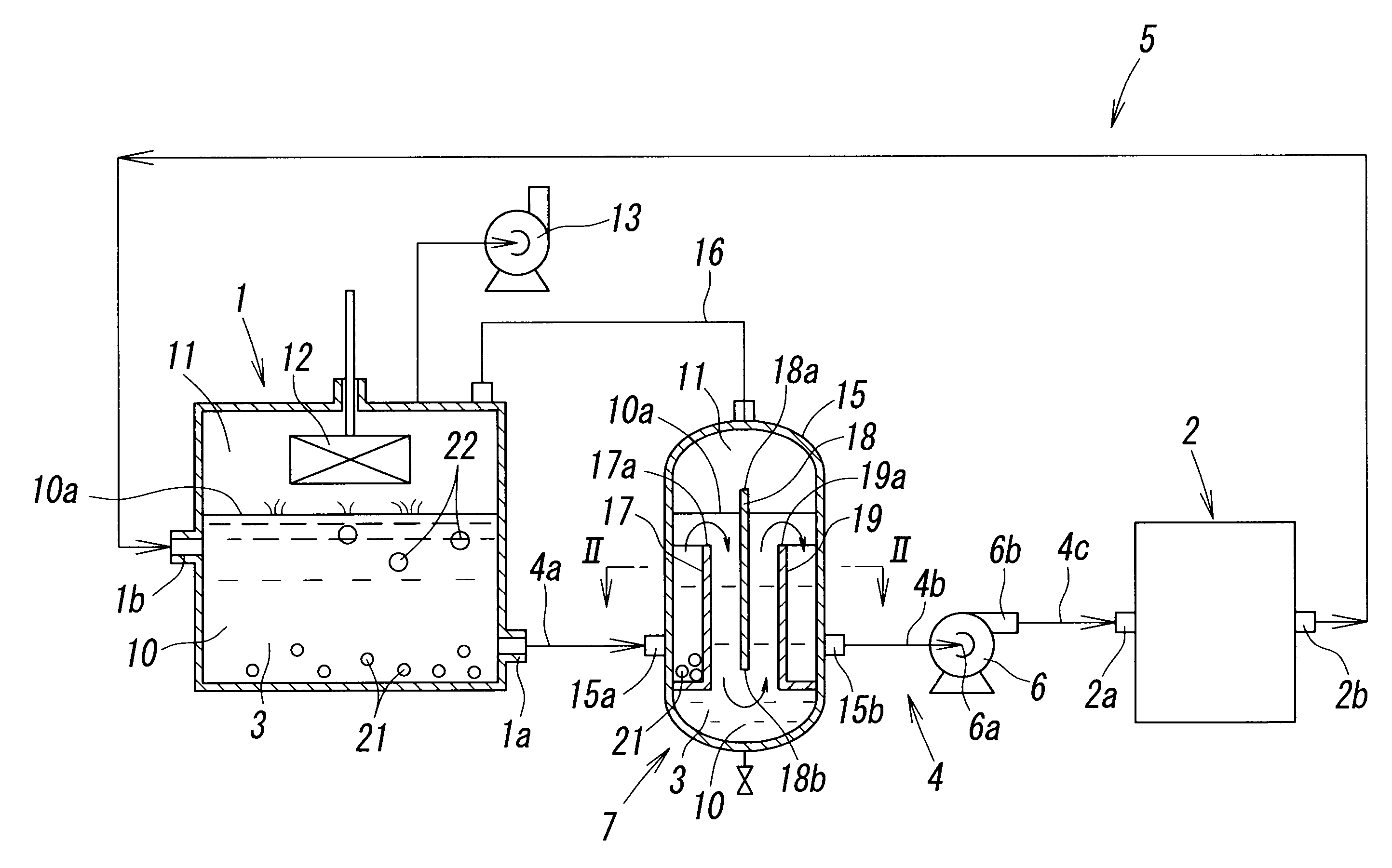
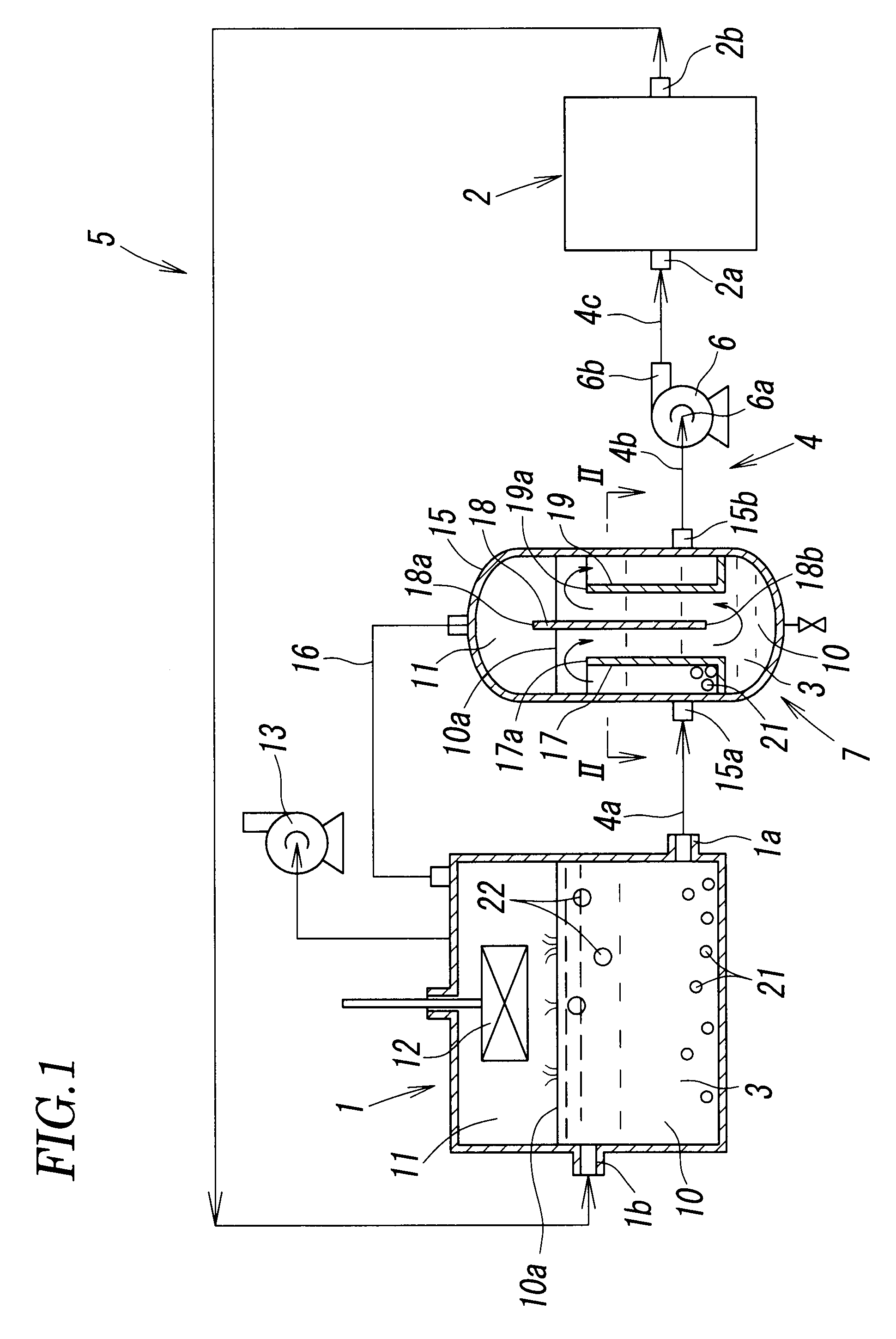
[0021]FIG. 1 and FIG. 2 show an external heating type reduced pressure fryer according to the invention. The reduced pressure fryer includes a frying tank 1 for immersing food to a heated oil 3 to subject to a frying treatment, an oil heating apparatus 2 installed at a location separately from that of the frying tank 1 for heating the oil 3, an oil transferring path 4 for transferring the oil 3 at inside of the frying tank 1 to the oil heating apparatus 2 by way of an oil transferring port 1a, an oil recirculating path 5 for recirculating the oil 3 heated by the oil heating apparatus 2 to the frying tank 1 by way of an oil flowing port 1b, a circulating pump 6 installed at a middle of the oil transferring path 4 for circulating the oil 3 between the frying tank 1 and the oil heating apparatus 2 by way of the oil transferring path 4 and oil recirculating path 5, and an oil / water separating portion 7 arranged along the oil transferring path 4 reaching the circulating pump 6 from the f...

second embodiment

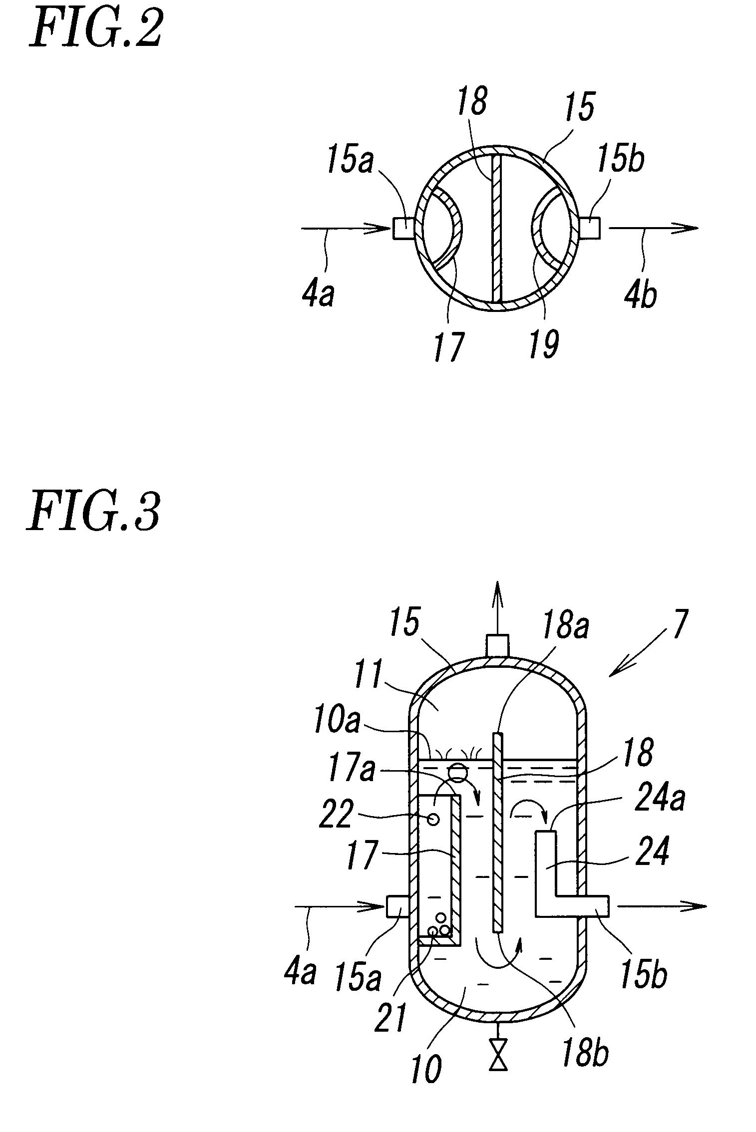
[0038]Even when a portion of the boiling water 22 exceeds the lower edge 18b of the second baffle plate 18 by riding on a flow of the oil 3, the boiling water 22 floats up at inside of the oil during a time period in which the oil 3 rises in a region in which the guide out pipe 24 is interposed on a downstream side of the second baffle plate 18 and is evaporated into the gas phase portion 11 substantially completely and is not brought into the guide out pipe 24 from a front end thereof.

[0039]Other constitution and operation of the second embodiment are substantially the same as those of first embodiment, and therefore, illustration and explanation of a total constitution thereof will be omitted.

[0040]Further, according to the first embodiment and the second embodiment, when the first baffle plate 17 is provided in the plurality of baffle plates, the water drop 21 sinking into the oil which is the most problematic can be interrupted to promote evaporation thereof, and therefore, eve...

third embodiment

[0046] in water provided into the oil by food in carrying out the frying treatment of the food, the water drop 21 sinking near to the oil bottom is interrupted by the first baffle plate 17 and is hampered from flowing into the oil transferring portion 26, stays awhile at the position, heated by the oil 3 at high temperatures to be brought into a state of the boiling water 22, rises in the oil and is evaporated into the gas phase portion 11 from the oil face 10a. Further, also the boiling water 22 discharged from the food rises in the oil and is evaporated into the gas phase portion 11 from the oil face 10a.

[0047]Even when a portion of water assumedly detours the upper edge 17a of the first baffle plate 17 along with the oil 3, flows to the oil transferring portion 26 and is transferred from the oil transferring port 1a to the separating tank 15, the water is evaporated at inside of the separating tank 15 by being interrupted by the second baffle plate 18 at inside of the separating...


PUM

PropertyMeasurementUnit
Pressureaaaaaaaaaa
Heightaaaaaaaaaa

Abstract

To provide an external heating type reduced pressure fryer capable of carrying out a cycle of heating and circulating an oil between a frying tank and a heating apparatus even when a frying treatment of a food is carried out in the frying tank, the external heating type reduced pressure fryer includes a frying tank for immersing the food to a heated oil to be subjected to a frying treatment, an oil heating apparatus for heating the oil, an oil transferring path and an oil recirculating path connecting the frying tank and the oil heating apparatus, a circulating pump installed in the oil transferring path, and an oil / water separating portion for removing water in the oil, the oil / water separating portion includes a first baffle plate for forming a flow path of detouring the oil bent in an up and down direction, the water in the oil is interrupted by the baffle plate during a time period of making the oil flow to a downstream side while detouring the first baffle plate to promote the water to evaporate to a gas phase portion by boiling.

Description

FIELD OF THE INVENTION[0001]The present invention relates to a fryer for immersing foods comprising various vegetables, fruits, marine products constituted by a thin plate shape, a stick-like shape, a dice-like shape or the like in a heated oil at inside of a frying tank under reduced pressure to subject to a frying treatment, particularly, relates to a reduced pressure fryer of an external heating type provided with a heating apparatus for heating an oil separately from the frying tank.BACKGROUND ART[0002]A reduced pressure fryer of an external heating type provided with a heating apparatus for heating an oil separately from a frying tank is publicly-known in a background art as disclosed in, for example, Patent Reference 1, Patent Reference 2 or the like. A reduced pressure fryer of this kind is constituted such that the frying tank and the heating apparatus are connected with each other by an oil transferring pipe and an oil recirculating pipe, a circulating pump is connected to ...

Claims


Application Information

Patent Timeline
IPC IPC(8): A47J37/12B01D35/02
CPCA47J37/1233
Inventor TAKAHASHI, KAZUO
Owner TAKAHASHI KAZUO
Learn More