Thin film systems and methods for using and making same

Inactive Publication Date: 2016-05-12
EMPIRE TECH DEV LLC
View PDF0 Cites 3 Cited by
  • Summary
  • Abstract
  • Description
  • Claims
  • Application Information

AI Technical Summary

Benefits of technology

[0003]In an embodiment, thin film systems configured to form a this film of a fluid to promote evaporation of the fluid may comprise an evaporation structure and at least one wiper blade configured to move over a top surface of the evaporation structure The evaporation structure may be configured to facilitate evaporation of a fluid on the top surface and within at least one channel formed within the top surface. The at least one wiper blade may comprise at least one protrusion corresponding to the at least one channel and may be configured to move over the top surface with at least a portion of the at least one protrusion moving within the at least one channel. The at least one wiper blade and the at least one protrusion may be arranged to be in contact with at least a portion of the fluid to form a thin film of the fluid on the top surface and within the at least one channel.
[0004]In an embodiment, a thin film vapor condensation system may comprise a source of a fluid, at least one condensation surface configured to facilitate condensation of fluid vapor thereon, and at least one evaporation structure configured to facilitate evaporation of the fluid on a top surface thereof and within at least one channel formed within the top surface. The thin film vapor condensation system may also include at least one wiper blade comprising at least one protrusion corresponding to the at least one channel. The at least one wiper blade may be configured to move over the fop surface with at least a portion of the at least one protrusion moving within the at least one channel. The at least one wiper blade and the at least one protrusion may be arranged to be in contact with at least a portion of the fluid to form a thin film of the fluid on the top surface and within the at least one channel. At least one heater may be configured to heat the thin film of fluid to generate a flow of fluid vapor toward the at least one condensation surface for condensation thereon.
[0005]In an embodiment, a method of forming a thin film of a fluid to promote evaporation of the fluid may comprise providing an evaporation structure configured to facilitate evaporation of a fluid on a top surface thereof and within at least one channel formed within the top surface and providing at least one wiper blade comprising at least one protrusion corresponding to the at least one channel. The at least one wiper blade may be position

Problems solved by technology

However, merely increasing the size of an evaporation surface or an evaporative heater may not improve the overall effectiveness of the system due to size, material and/or cost restrictions.
In addition, conventional evaporation surfaces

Method used


Image

  • Thin film systems and methods for using and making same
  • Thin film systems and methods for using and making same
  • Thin film systems and methods for using and making same

Examples


Example

Example 1

Water Distillation Process using Thin Film Wiper Systems

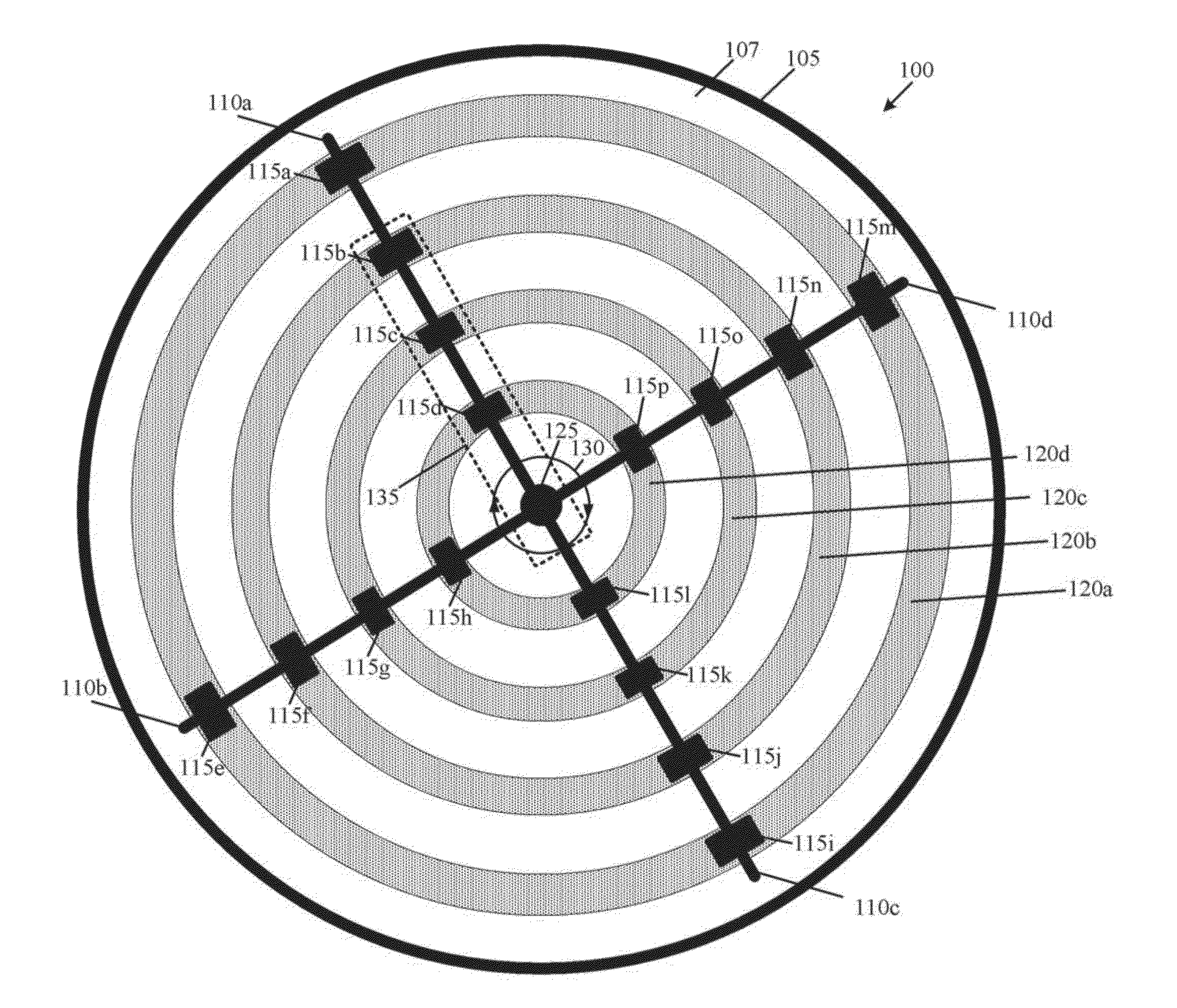
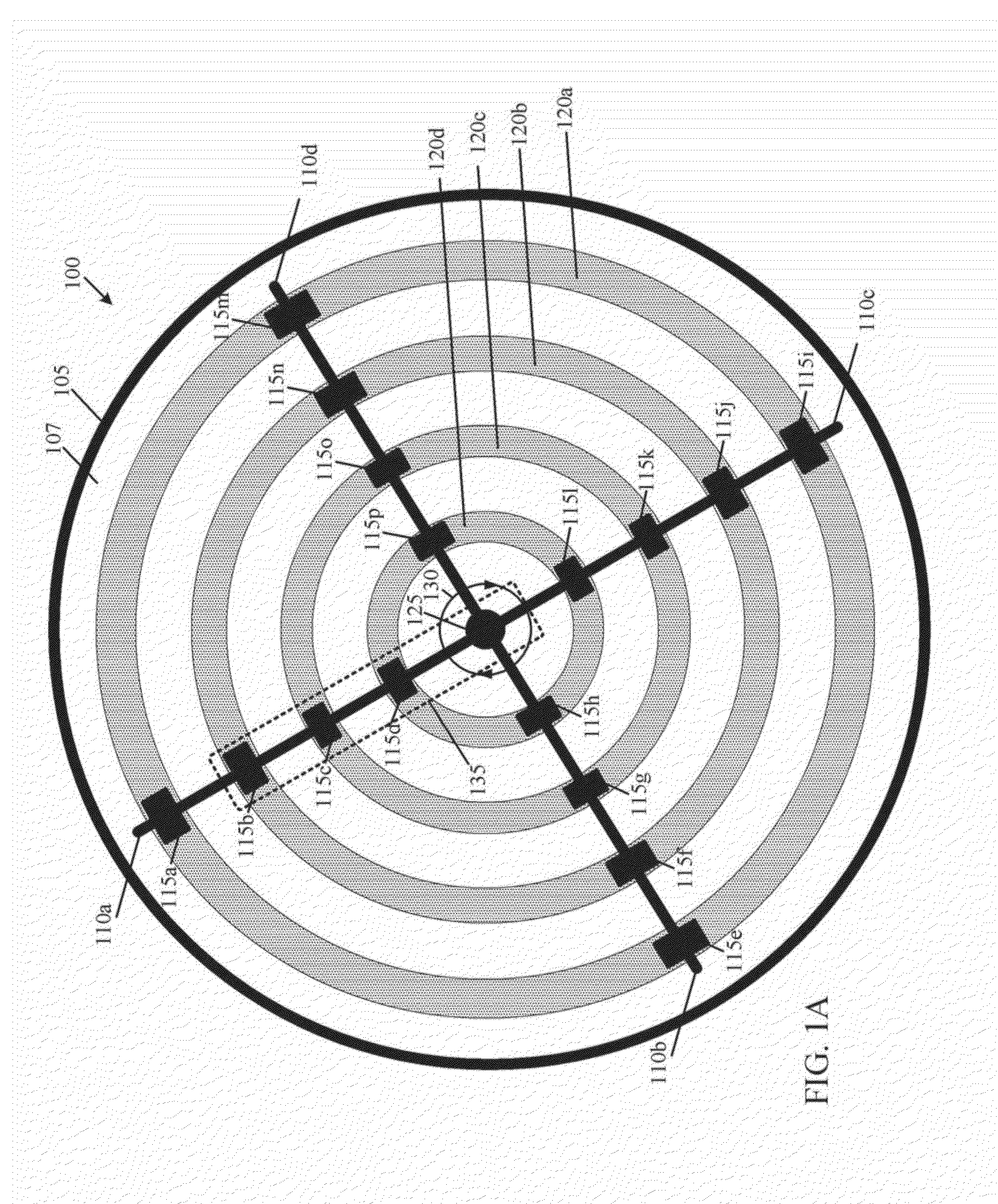
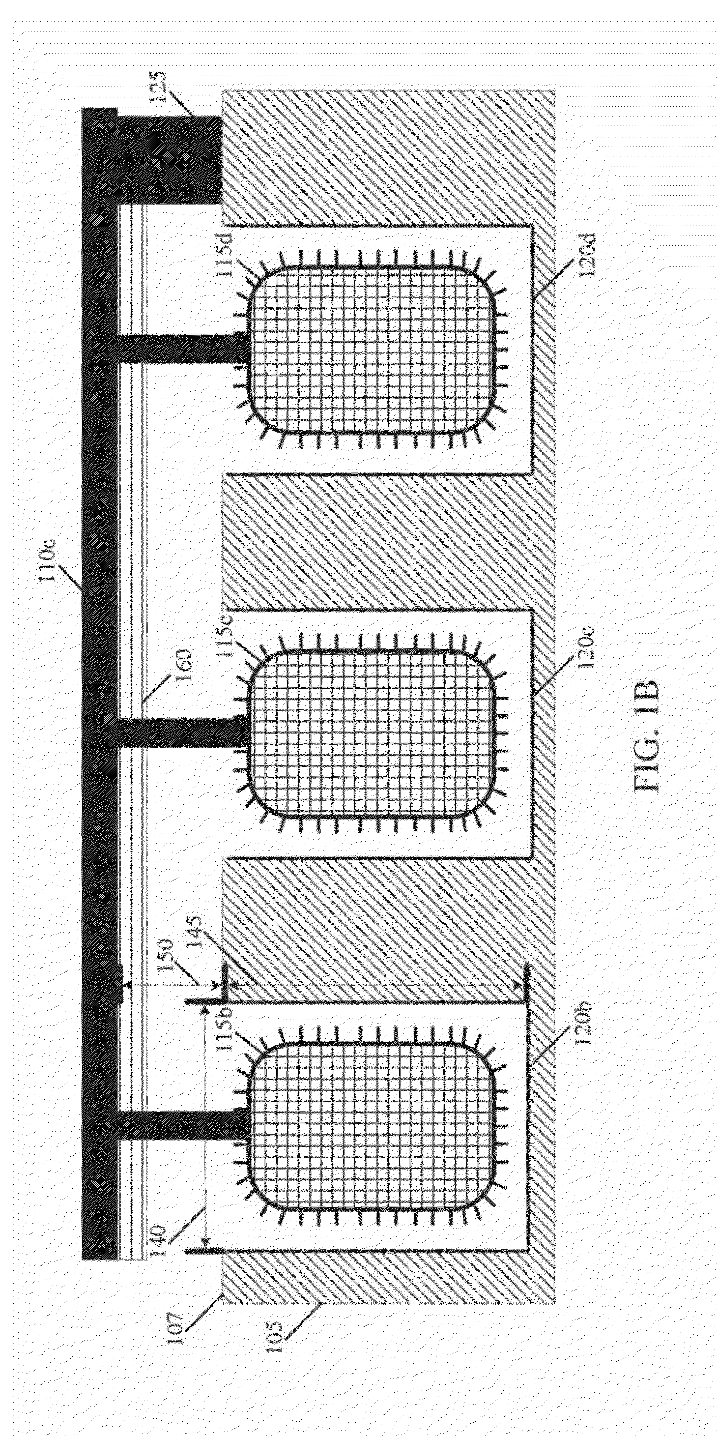
[0048]A water distillation facility will be equipped with 5 circular evaporation structures arranged within a distillation room, each having a diameter of about 3 meters and a thickness of about 0.5 meters. The evaporation structures will be formed of carbon steel. The evaporation structures will have 4 circular channels having a depth of about 5 centimeters and a width of about 8 centimeters formed within a top surface of the evaporation structures spaced about 0.5 meters apart starting from a central axis of each evaporation structure.

[0049]Each of the condensation structures will have two thin film wiper blades formed from carbon steel and an edge formed from a rubber material. The thin film wiper blades will include a protrusion for each channel formed from a polyvinyl chloride mesh structure. Each protrusion will have a height of about 4 centimeters and a width of about 7 centimeters. The thin film wiper blades wi...

Example

Example 2

Horizontal Thin Film System

[0052]A computing system will include a heat transfer system configured to cool a central processing unit (CPU). The heat transfer system will be configured as a heat pipe having a chamber made of a nickel alloy and will have a thickness of about 100 millimeters, a width of about 2 centimeters, and a height of about 0.5 centimeters. The chamber will include an evaporation surface located on the side of the chamber contacting the CPU and a condensation surface on the opposite side of the chamber.

[0053]A belt system including a first wheel and a second wheel arranged oh a horizontal plane and having a rubber belt wound around the first wheel and the second wheel will be arranged within the chamber. The first wheel will be mechanically coupled with an electric motor configured to rotate the first wheel, thereby causing the belt and the second wheel to rotate. The belt will be learned with ribbed protrusions on an outside surface thereof (the surface ...


PUM

PropertyMeasurementUnit
Thicknessaaaaaaaaaa
Thicknessaaaaaaaaaa
Thicknessaaaaaaaaaa

Abstract

Systems and methods for generating a thin film of a fluid are described. In an embodiment, a fluid support structure may be configured to receive a fluid, such as water, at a top surface and to support the fluid over at least a portion of the top surface. Channels may be formed in the top surface of the fluid support structure. Wiper blades may be configured to move over the top surface in contact with at least a portion of the fluid to form the fluid into a thin film. The wiper blades may include protrusions corresponding to the channels. As the wiper blades move over the top surface, the protrusions may move within the channels forming a thin film of the fluid within the channels. According to some embodiments, the fluid support structure may be configured as an evaporation surface configured to facilitate the evaporation of the fluid.

Description

BACKGROUND[0001]Evaporation-condensation heat transfer systems operate through an evaporation-condensation cycle that facilitates the movement of heat between two surfaces. These heat transfer systems include a heated evaporation surface that evaporates a fluid into a vapor. The vapor travels toward a condensation surface having a temperature that is cool enough to condense the vapor into a liquid. Evaporation-condensation heat transfer systems are used by processes such as water desalination, oil refining and industrial cooling for various purposes, including reducing unwanted heat or removing certain particles from a liquid.[0002]A factor in the efficiency of evaporation-condensation heat transfer systems is the evaporation rate of the fluid. For example, if the evaporation surface is larger or if more heat is applied to the fluid, more fluid may be evaporated per unit of time. However, merely increasing the size of an evaporation surface or an evaporative heater may not improve t...

Claims


Application Information

Patent Timeline
IPC IPC(8): B01D1/22C02F1/08F28C3/00H05K7/20
CPCB01D1/225F28C3/005C02F1/08H05K7/20309B01D5/0024B01D5/006
Inventor WANG, HAO
Owner EMPIRE TECH DEV LLC
Why Eureka
Try Eureka